Home / Solutions / Aviation & Transportation Hubs / Modern Railway Stations

Mega-Span Steel Structures for Modern Railway Stations & High-Speed Rail Hubs

The Civil Backbone.

Engineered for high-speed rail aerodynamics, massive passenger throughput, and zero-disruption live-track construction. We design and manufacture heavy-duty structural steel for elevated station concourses, 450m+ column-free platform canopies, and Bridge-Station Integrated transit hubs. From resisting 350 km/h train slipstream fatigue to executing precision hydraulic sliding over active 27.5kV rail lines during midnight maintenance windows, we deliver iconic, maintenance-free rail gateways on schedule.

Industry Challenges & Solutions

A railway station is an active industrial artery combined with a high-density public building. A single loose roof panel falling onto the tracks or a 30-minute delay during a track-possession window can paralyze a national rail network. We solve the exact headaches that keep railway chief engineers and station operators awake at night.

THE CHALLENGE

When a high-speed train rockets through a station at 300–350 km/h without stopping, it generates a violent positive-to-negative aerodynamic pressure wave (slipstream/piston effect). Combined with natural crosswinds, this repeated dynamic buffeting fatigues standard roof purlins and rips thin metal sheets right off the canopy—dropping debris directly onto the 27.5kV high-voltage catenary wires below and halting all trains.

SynJect ENGINEERED SOLUTION

We engineer Aero-Fatigue Resistant Tubular Trusses & Double-Locked Anti-Suction Envelopes We calculate millions of train-pass aerodynamic fatigue cycles, reinforce canopy leading edges, and deploy 0.9mm–1.2mm thick Aluminum-Magnesium-Manganese standing seam roofs secured with heavy-duty external wind-locking clips—guaranteeing zero panel detachment under extreme slipstream and typhoon loads.

THE CHALLENGE

Upgrading an existing station or erecting a concourse over live railway tracks means you cannot shut down train operations. With 27.5kV high-voltage overhead wires running underneath, crane booms cannot swing freely during the day, and railway authorities only grant a strict 90-to-180-minute midnight “Maintenance Window” for overhead work.

SynJect ENGINEERED SOLUTION

We utilize Cumulative Hydraulic Rail-Sliding with Integrated Bottom Safety Shields We assemble the mega-span steel roof trusses alongside a safe zone off the tracks, complete with a solid bottom protective deck underneath. During midnight windows, computer-synchronized hydraulic jacks slide the entire assembled structure across the tracks—achieving zero falling-object risk and zero daytime train disruption.

THE CHALLENGE

Modern hubs use an “Elevated Waiting Hall over Viaduct Tracks” design. Heavy trains braking and accelerating directly beneath the waiting concourse send continuous low-frequency structural vibrations up the columns. If unmitigated, waiting passengers feel dizzying floor tremors, commercial glass facades crack, and steel welds suffer premature fatigue failure.

SynJect ENGINEERED SOLUTION

We engineer Concrete-Filled Steel Tubular (CFST) Columns & Cast Steel Transfer Nodes By combining thick-walled box/tubular steel columns filled with high-strength concrete and isotropic Cast Steel Nodes at multi-branch intersections, we drastically increase structural damping and fatigue life—isolating track vibrations so the waiting hall above remains rock-solid.

THE CHALLENGE

During peak travel rushes, a major station handles 150,000+ passengers daily. Dense columns in the departure hall create dangerous crowd-crush bottlenecks at security checkpoints and ticket gates. Down on narrow railway platforms, traditional canopy support pillars block passenger flows, luggage carts, and train driver sightlines, increasing the risk of passengers falling onto the tracks.

SynJect ENGINEERED SOLUTION

We manufacture 80m–150m+ Clear-Span Concourse Roofs & Transverse Column-Free Platform Canopies. Our spatial pipe trusses span across 6 to 12 tracks in a single leap, placing support columns entirely outside the active platforms or between tracks—creating 100% obstacle-free platforms and panoramic, column-free waiting halls.

THE CHALLENGE

High-speed rail platforms are 450 meters long to fit 16-car trainsets. Across seasons, a 450m continuous steel canopy expands and contracts by up to ±200mm, which can shear anchor bolts and crack roof seams. Worse, metallic brake dust from train wheels and acid rain corrode overhead steel—and because it sits over live 27.5kV wires, you can never erect scaffolding to repaint it.

SynJect ENGINEERED SOLUTION

We integrate Spherical Thermal Sliding Bearings & 50-Year Zero-Maintenance Fluorocarbon/Arc-Spray Coating Systems . Engineered expansion joints and sliding bearings let the 450m roof “breathe” stress-free, while our thermal-sprayed zinc-aluminum + PVDF coating guarantees a 50-year maintenance-free lifespan above live tracks.

Technical Specifications

The following table is intended for preliminary discussion and option assessment. These ranges are not universal design standards. Final parameters must be based on approved architectural and railway design information, equipment loads, site conditions and structural calculations.

Parameter Category Station Engineering Standard Real-World Station Value
Customization Available
Concourse Clear Span 72m – 150m+ (3D Spatial Tubular Truss / Space frame / Beam-String System) 100% column-free waiting concourse eliminating crowd bottlenecks at security and ticket gates.
Vertical Transfer Columns Bifurcated Tree-Shaped Steel Columns + Concrete-Filled Steel Tubes (CFST) Resolves mismatched column grids between underground subways, ground rail tracks, and upper halls.
Architectural Exposed Steel AESS Category 3/4 Standard: CNC 3D twisted box-sections, hidden bolts, flush-ground welds Delivers museum-grade visual smoothness for exposed interior structures with zero ceiling cover.
Complex Multi-Arm Nodes Custom One-Piece Solid Cast Steel Nodes (Grade G20Mn5QT isotropic cast steel) Creates smooth organic transitions where 6 to 10 curved branches meet, eliminating weld fatigue.
Elevated Waiting Floor Heavy Built-Up Steel Box-Girders + Composite Truss Deck (Live load: 6.0 – 10.0 kN/m²) Supports dense holiday passenger crowds, heavy X-ray security scanners, and TOD retail food courts.
Passenger Vibration Comfort Fundamental floor frequency > 5.0 Hz with Tuned Mass Dampers (Peak acceleration ≤ 0.05 m/s²) Isolates lower-level train braking tremors and footstep resonance so seated passengers feel zero sway.
Curtain Wall Decoupling Multi-directional telescopic sliding joints (±60mm vertical / ±40mm horizontal allowance) Prevents 100m+ steel roof thermal/wind deflection from crushing 25m-high glass curtain walls below.
Skylight & Shading Grid Structural steel skylight grid with integrated parametric shading louvers + Low-E laminated glass Floods concourse with soft natural daylight, stops screen glare, and cuts summer HVAC cooling by 35%.
Acoustic Roof Assembly Micro-perforated acoustic Al-Mg-Mn liner + high-density acoustic wool (RT60: 1.8 – 2.2s) Eliminates cavernous hall echoes so train boarding PA announcements are crystal-clear everywhere.
Platform Canopy Span 45m – 105m transverse span over 6–12 tracks; 450m longitudinal coverage (16-car trainset) Removes all pillars from narrow platforms for safe boarding, clear sightlines, and luggage cart flow.
350km/h Slipstream Defense Rated for ±3.0 kN/m² train piston-wind cycles; 1.0mm double-locked standing seam + wind clips Prevents passing high-speed train suction waves from ripping roof sheets onto 27.5kV catenary wires.
Thermal Expansion Control Spherical Articulated Sliding Bearings + thermal expansion joints (±200mm movement capacity) Allows 450m ultra-long station roofs and canopies to expand and contract safely from -30°C to +45°C.
Heavy Escalator Integration Factory-welded corbels for 100+ public-transit escalators (10m–18m rise, deflection < L/1000) Enables plug-and-play drop-in installation for heavy transit escalators and panoramic glass elevators.
FIDS & MEP Payloads Pre-engineered 5 – 20 Ton bottom-chord hanger nodes + Cellular Beams for oversized ducts Safely suspends giant LED train departure boards (FIDS), wayfinding signage, and jet-nozzle HVACs.
Fire & Smoke Compliance 2.5 to 3.0-Hour Fire Rating (Ultra-thin aesthetic intumescent paint) + smoke louver framing Protects structural integrity during mass evacuation without ruining exposed steel aesthetics.
Roof Unloading Precision 3D laser-scanned factory trial assembly + staged hydraulic unloading (Elevation error ≤ ±5mm) Guarantees exact roof settlement geometry so curtain wall and rail signaling teams start on day one.

NoteSite geotechnical data and authority approvals shall be reviewed before the structural design is finalized.

From Digital to Terminal Handover

From early structural and railway-interface coordination to fabrication, erection and handover, each stage is planned around the practical requirements of station buildings and railway operations.

PHASE 01 / PRE-CONSTRUCTION

Design & 3D BIM Modeling

Our rail structural engineers build a 1:1 LOD 400 digital twin using Rhino, Grasshopper, and Tekla—resolving multi-level load paths, free-form roof geometry, and multi-trade interfaces before cutting any steel.

PHASE 02 / CONSTRUCTION

On-Site Structural Frame Erection

Factory trial-assembled steel components arrive on site for rapid, laser-guided erection. We deploy modular block-lifting and synchronized hydraulic unloading to erect the massive station skeleton safely and ahead of schedule.

PHASE 03 / COMPLETION

Project Completion & Operational Handover

Following scientific staged unloading, the structural frame seamlessly receives the glass curtain walls, acoustic skylights, and rail systems—handing over an iconic, bright, and comfortable transit hub ready for national rail operation.

Qualification Certificate

Your projects are protected by world-class standards. From CE (EN 1090) to ISO 9001, our qualifications are not just paper—they are the rigorous daily reality on our shop floor.

AISCCEOTCInternational Welder
ISO 9001 Quality Management System

Recommended Product Systems

Space Frame Structure

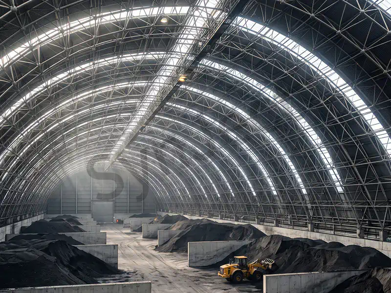
SynJect Space Frame structures provide exceptional 3D stability for large-span architectural designs.

Steel Truss

SynJect Steel Truss systems deliver unparalleled heavy load-bearing capacity and clear-span flexibility.

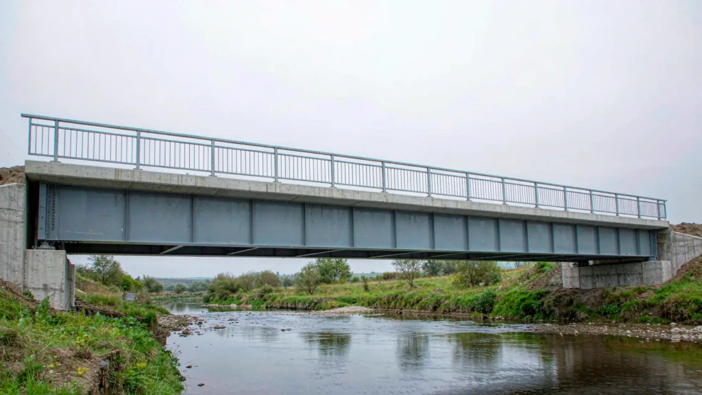
Single-span steel box girder bridge with concrete abutments and steel railing crossing a river

SynJect manufactures heavy-duty steel bridge structures designed to withstand millions of dynamic load cycles. Operating an 80,000 m² facility, we fabricate complex plate girders, box girders, and pedestrian truss bridges strictly compliant with EN 1090-2 EXC2 and AISC standards for global public infrastructure.

Completed steel structure cladding system project delivered by SynJect

SynJect Envelope & Cladding Systems seal your structures with superior thermal performance and weatherproofing.

Frequently Asked Questions

How do you handle the completely different column grids on each floor?

This is the core structural challenge of "City-Station Integrated" hubs. Because ground columns can only stand in the narrow gaps between train tracks, we engineer a Heavy Steel Box-Girder Transfer Story combined with Bifurcated "Tree-Shaped" Columns . A single high-strength Concrete-Filled Steel Tubular (CFST) column rises between the tracks and branches outward like a tree canopy into 4 to 8 arms—simultaneously supporting the elevated waiting hall floor grid and the 100m+ column-free roof above without blocking a single train track or subway corridor.

For passenger-facing areas, we strictly fabricate to AESS (Architecturally Exposed Structural Steel ) standards rather than standard industrial codes. First, we replace messy multi-plate welded intersections with smooth, one-piece Cast Steel Nodes . Second, we design Concealed Internal Flange Splices so no bulky bolt clusters are visible from the outside. Third, all field butt-welds are ground completely flush and filled before applying a smooth fluorocarbon topcoat—giving 80-ton structural columns the seamless finish of an art sculpture.

Any 120m span roof will naturally deflect by several centimeters under heavy snow, wind, or seasonal temperature swings. To protect the brittle glass, we engineer Multi-Directional Displacement-Decoupling Joints where the steel roof meets the facade, and we apply Pre-Camber Compensation during fabrication. The telescopic joints allow the massive steel roof to move vertically (±60mm) and horizontally (±40mm) completely independently of the glass wall—ensuring zero crushing stress on the glass and 100% waterproof skylight seals.

Sitting passengers are 10 times more sensitive to low-frequency floor vibrations than walking shoppers. If the floor resonates at 2–3 Hz, passengers feel motion sickness. During the BIM phase, we run strict Human-Comfort Dynamic Time-History Analysis . We stiffen the elevated floor using deep welded steel box-girders (forcing the natural frequency above 5.0 Hz) and install Tuned Mass Dampers inside the floor cavity. This locks peak vertical acceleration below 0.05 m/s², making the elevated hall feel like solid ground.

When a concourse is enclosed in bare steel and glass, sound waves bounce around for 4 to 5 seconds (RT60), turning PA broadcasts into unintelligible noise. We integrate a Multi-Layer Acoustic & Thermal Roof System directly into our structural purlin grid. The bottom layer facing passengers uses micro-perforated aluminum-magnesium-manganese acoustic panels backed by non-woven acoustic fleece and high-density rock wool. This absorbs ambient crowd noise and locks reverberation time around 1.8 to 2.2 seconds, ensuring high speech intelligibility (STIPA ≥ 0.55) across the entire hall.

If you manufacture every curved beam using custom molds by hand, costs explode and site assembly fails. We use Parametric Geometry Optimization (Rhino + Tekla) to rationalize free-form surfaces into standardized families of CNC-bent tubes or 3D Twisted Box-Girders . In our factory, robotic multi-axis bending machines and 6-axis laser cutters produce each unique member directly from digital coordinates. We then perform 3D Laser-Scanned Virtual & Physical Pre-Assembly before shipping, guaranteeing 100% on-site fit-up at a controlled factory cost.

On-site cutting or re-welding on primary station girders is strictly forbidden by railway quality codes. During Step 1 (BIM Detailing), we import the exact shop drawings from your escalator manufacturer and Passenger Service System vendor. We pre-weld all heavy Escalator Support Corbels , mid-span suspension points, and 15-to-20-Ton FIDS Rigging Nodes directly onto the steel beams in our factory. When the escalator and IT teams arrive on site, they simply drop their equipment onto pre-aligned brackets.

Roof unloading is the most critical moment in station construction. Before erection, our engineers run a Full-Process Staged Unloading Simulation to calculate the exact elastic deflection of every node, building an upward "Pre-Camber" into the factory steel. On site, we do not just knock out supports; we use Computer-Synchronized Hydraulic Jacks to lower the roof in 5 to 10 millimeter increments while monitoring stress gauges and laser targets in real time—settling the roof within ±5mm of its theoretical elevation.

For the 450m length, we install Spherical Articulated Sliding Bearings and expansion joints that allow the canopy to silently expand and contract by ±200mm across winter and summer without cracking. To defeat the violent positive-to-negative pressure wave ("Piston Wind") of 350 km/h trains, we design Transverse Column-Free Tubular Canopies clad in 1.0mm thick Al-Mg-Mn double-locked standing seam panels secured with external heavy-duty wind-locking clips—guaranteeing zero loose panels over the 27.5kV catenary wires for 50 years.

Please share: 1) Architectural & Structural Design Institute Drawings (CAD plans/sections, or Rhino/Tekla 3D models);

2. Station Scale & Layout Info (elevated concourse span, platform canopy type, AESS exposed steel requirements, and target opening schedule);

3. Local Load Codes (wind, snow, seismic intensity, and seasonal temperature range). Our railway station engineering team will provide a 3D node optimization plan, an unloading/erection methodology, and an itemized fixed-budget quotation.

Get Your 24-Hour BOQ and Cost Plan

See how much steel tonnage and ocean freight you can save before fabrication begins

8–15%

Steel Weight Savings

1:1 Tekla 3D modeling optimizes beam-column ratios to eliminate redundant material costs.

0.0mm

Zero-Clash Code Verification

Checked against EN 1090 and local wind/seismic loads.

100%

Engineer-to-Engineer Review

Verified by our lead engineers—Zero pushy sales calls, Just actionable data and factory price.

CE EN 1090-1•ISO 9001•ISO 14001•ISO 45001

Engineering & Inquiry Desk

Lead Engineers Online

Drawings
Drawings

🔒 100% Private and Secure, No Spam