Home / Products / Steel Truss / Bracing System
Bracing System
Steel Column Bracing · Roof Horizontal Bracing · Flange Brace · Sag Rod · Steel Purlin Spacer Tube · Steel Gutters · Eave Strut Purlin
What we fabricate in this sub-system
Steel Truss Steel Column Bracing
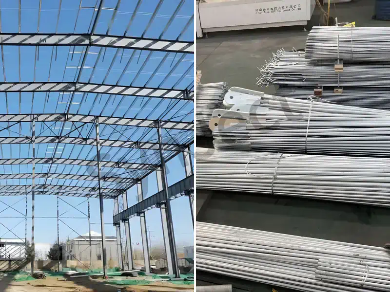
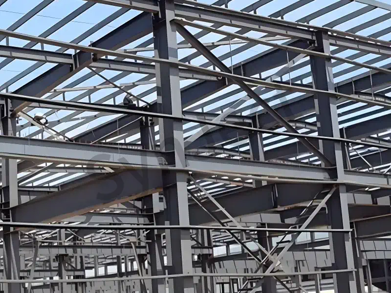
Steel Column bracing (inter-column bracing) is a bracing system installed between adjacent longitudinal column rows in a plant. It withstands the plant's longitudinal horizontal loads (crane longitudinal braking forces, wind loads, seismic action) and ensures the plant's longitudinal stiffness and overall stability. By layout position, it can be divided into upper column bracing and lower column bracing; by form, into cross (X) bracing, V-bracing (chevron), inverted V-bracing, and portal bracing. Column bracing, together with roof transverse bracing and Eave Strut Purlin, forms a spatial geometric invariable system, acting as a critical component for the plant's longitudinal seismic and wind resistance.
Technical Specifications
| Parameter | Specification |
|---|---|
| Common Forms | Cross bracing, V-bracing, inverted V-bracing, portal bracing |
| Section Forms | Round steel, angle steel, circular tube, H-beam, rolled channel steel |
| Material | Q235B, Q355B |
| Installation Position | Middle column rows of the plant's temperature section |
| Function | Transfer longitudinal horizontal forces, ensure longitudinal stiffness |
| Connection Method | Welded or bolted via gusset plates to the columns |
| Material Specifications | Commonly ø20, ø25 round steel, L75×5~L140×10 double angle steel built-up sections |
| Tensioning Device | Cross round steel bracing can be equipped with turnbuckles for tensioning |
| Layered Setup | Upper column bracing (above crane beams) and lower column bracing (below crane beams) |
| Execution Standard | GB 50017, GB 51022 |
Values are the range we fabricate routinely. Project-specific sizes, grades and coating systems are confirmed on the approved shop drawing before release to production.
Advantages vs Engineering Considerations
| Advantages | Engineering Considerations |
|---|---|
| Improves longitudinal stiffness: Significantly reduces plant longitudinal lateral drift, ensuring overall structural stability. | Affects building usage: Cross bracing may interfere with doors and process layouts; coordination with architecture is needed. |
| Transfers horizontal forces: Effectively transfers crane longitudinal braking forces, wind loads, and seismic action. | Heavy gusset plate welding: Cross bracing gussets involve many welds; welding deformation must be controlled. |
| Flexible layout: Cross, V-shape, and portal forms adapt to various process and doorway requirements. | Tensioning degree must be controlled: Round steel cross bracing must be tensioned during installation, otherwise it is ineffective. |
| Material-saving: Bracings are designed as two-force members, requiring little steel. | Temperature section layout: Bracing should be located in the middle of a temperature section to avoid temperature stress concentration. |
| Factory prefabrication: Members fabricated in the factory, bolted on-site. | Seismic nodes must follow codes: Bracing nodes in seismic zones must be designed according to seismic levels. |
Frequently Asked Questions
What is the function of steel column bracing?
Ensures longitudinal stiffness of the plant, transfers longitudinal horizontal forces, and prevents lateral drift instability.
What are the forms of column bracing?
Cross bracing, V-bracing, inverted V-bracing, portal bracing.
How to distinguish upper and lower column bracing?
Above the crane beams is upper bracing; below is lower bracing, bearing horizontal forces at different heights.
What materials are commonly used for column bracing?
Round steel sections (for hinged bases without cranes), double angle sections (with cranes); large spans may use tubes or H-beams.
Where is column bracing installed?
In the middle and ends of the plant's temperature section column rows to avoid excessive temperature stress.
Why must cross round steel bracing be tensioned?
To prevent slack and ensure immediate action when subjected to tension.
What is the relationship between column bracing and Eave Strut Purlin?
Column bracing + roof transverse bracing + Eave Strut Purlin form a spatial geometric invariable system.
How to handle column bracing if there are doorways?
Can switch to portal bracing or inverted V-bracing to bypass doorways.
How are column bracing nodes connected?
Welded or high-strength bolted to the column side connection plates via gusset plates.
What are the requirements for column bracing in seismic zones?
Bracing diagonal slenderness ratio, gusset plate thickness, and connection welds must be strengthened per seismic levels.
Steel Truss Roof Horizontal Bracing
Roof Horizontal bracing is a bracing system arranged in the plane of the upper or lower chords of the roof truss (or rigid frame). Together with column bracing and Eave Strut Purlin, it forms the spatial stability system of the plant. By position, it can be divided into upper chord transverse horizontal bracing, lower chord transverse horizontal bracing, lower chord longitudinal horizontal bracing, and skylight frame bracing. Horizontal bracing bears gable wind loads and crane transverse horizontal braking forces, transferring them to the column bracing. It also ensures the in-plane stiffness of the roof, preventing buckling. Common forms are cross round steel or angle steel, installed in the first or second bays at both ends of a temperature section.
Technical Specifications
| Parameter | Specification |
|---|---|
| Layout Position | Roof truss upper/lower chord planes, arranged along bays |
| Common Forms | Cross round steel, cross angle steel, crisscross |
| Round Steel Diameter | commonly φ20, φ25) |
| Angle Steel Spec | L50×5~L90×6 |
| Material | Q235B |
| Setup Principle | First or second bay at both ends of the temperature section |
| Tensioning Device | Round steel bracing equipped with turnbuckles |
| Connection | Bolted to the roof truss gusset plates |
| Function | Transfer roof horizontal forces, ensure roof in-plane stiffness |
| Execution Standard | GB 50017, GB 51022 |
Values are the range we fabricate routinely. Project-specific sizes, grades and coating systems are confirmed on the approved shop drawing before release to production.
Advantages vs Engineering Considerations
| Advantages | Engineering Considerations |
|---|---|
| Ensures roof in-plane stiffness: Turns the roof into a rigid disc, effectively transferring horizontal forces. | Affects roof truss lower chord headroom: Cross bracing may affect pipeline layouts and requires coordination. |
| Transfers gable wind loads: Gable wind loads are transferred to column bracing via horizontal bracing. | Tensioning must be controlled: Slack means failure; must be tensioned during installation. |
| Material-saving: Cross round steel is designed for tension, using very little steel. | Numerous gusset plates: Every panel point has gusset plates, demanding heavy fabrication work. |
| Flexible layout: Can be adjusted according to doors and skylight positions. | Temperature section setup: Must be arranged at both ends of the temperature section without omission. |
| Simple installation: Bolted connection, tensioned via turnbuckles. | Rust risk: Round steel is thin and must be galvanized for anti-corrosion. |
Frequently Asked Questions
What is the function of horizontal bracing?
Ensures roof in-plane stiffness, transfers gable wind loads and crane transverse braking forces.
What is the relationship between horizontal bracing and column bracing?
Horizontal bracing + column bracing + Eave Strut Purlin form a spatial stability system.
What materials are used for horizontal bracing?
commonly cross round steel Φ20~φ40, or cross angle steel.
Where is horizontal bracing installed?
The first or second bay at both ends of a temperature section.
Why must horizontal bracing be tensioned?
Round steel cross bracing only bears tension; if slack, it cannot transfer forces promptly.
How is horizontal bracing arranged with skylights?
Skylight frames also need bracing, coordinated with roof truss lower chord bracing.
What is the difference between horizontal bracing and Eave Strut Purlin?
Horizontal bracing uses a crossed layout to transfer horizontal forces; Eave Strut Purlin are longitudinal to reduce compressive effective length.
Can horizontal bracing be omitted?
No, omitting it makes the roof geometrically variable, lacking seismic and wind resistance.
How are horizontal bracing nodes connected?
Bolted via bolt holes on the roof truss gusset plates.
How to do anti-corrosion for horizontal bracing?
Hot-dip galvanizing or anti-rust paint + topcoat.
Steel Truss Sag Rod
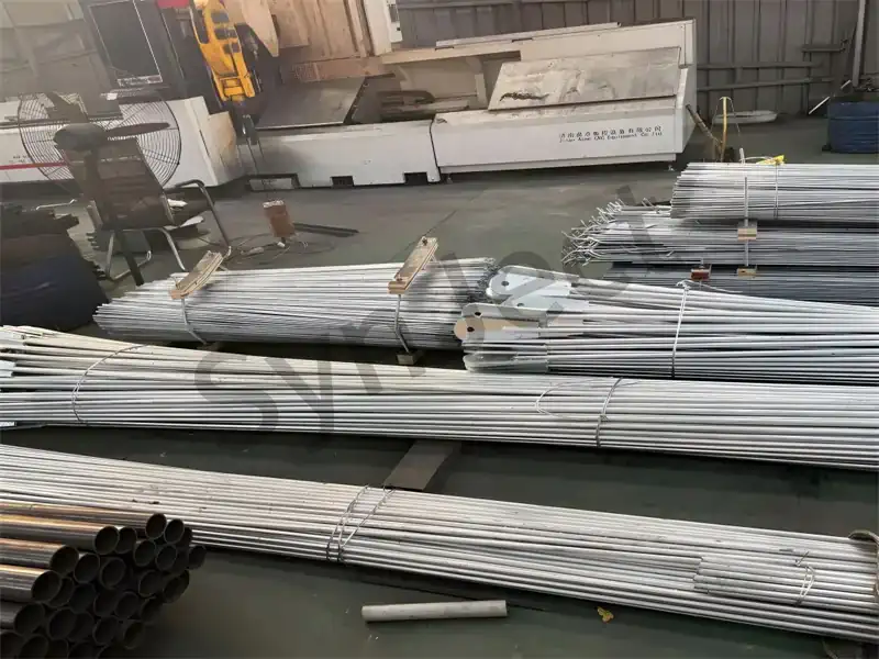
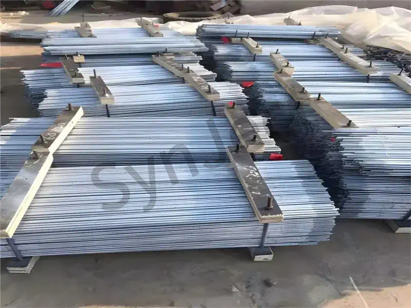
Sag rods (Eave Strut Purlin) are slender round steel tension members installed in the roof and wall girt systems of lightweight steel structures. They connect adjacent purlins or wall girts to reduce the out-of-plane effective length of the members, preventing purlins (or girts) from lateral bending and torsional deformation under wind loads, dead weight, and roof loads. Sag rods typically use HPB300 round steel with common diameters of φ12 or φ14, connected to the purlin web via bending or threaded ends with bolts. Diagonal sag rods and struts are usually installed at the ridge of double-pitch roofs to form a stable geometric invariable triangular system.
Technical Specifications
| Parameter | Specification |
|---|---|
| Common Materials | HPB300 round steel (Q235) |
| Diameter | commonly φ12) |
| Layout Spacing | Based on purlin span: 4~6m generally 1 row, 6~9m generally 2 rows, above 9m generally 3 rows. |
| Connection Method | Threaded ends, bolted to purlin web |
| Accessories | Diagonal sag rod, steel purlin spacer tube (tube) |
| Installation Position | Near the upper flange or center of the purlin web |
| Tensioning Requirements | Must be pulled straight and tensioned during installation; no slack allowed |
| Anti-corrosion Treatment | Hot-dip galvanizing or anti-rust paint |
| Installation Tools | Wrench, tensioner |
| Execution Standard | GB 51022 |
Values are the range we fabricate routinely. Project-specific sizes, grades and coating systems are confirmed on the approved shop drawing before release to production.
Advantages vs Engineering Considerations
| Advantages | Engineering Considerations |
|---|---|
| Simple structure: Round steel sag rods are easy to source and low cost. | Tension degree must be controlled: Too loose provides no support; too tight may deform the purlins. |
| Significantly improves purlin stability: Reduces the out-of-plane effective length of purlins, preventing flexural-torsional buckling. | Rust risk: Slender round steel easily rusts; requires galvanizing or painting and maintenance. |
| Convenient installation: Threaded ends, on-site bolting, fast construction. | Connection nodes prone to loosening: Nuts may loosen under long-term vibration; regular checks needed. |
| Adjustable: Sag rod tightness can be finely adjusted via nuts. | Densification needed in high-wind areas: Steep slopes and large wind suction zones require denser sag rod spacing. |
| Mature accessory system: Forms a complete bracing system with steel purlin spacer tube, diagonal sag rods, and struts. | Cannot bear compression: Sag rods can only bear tension; compression zones require steel purlin spacer tubes. |
Frequently Asked Questions
What is the function of a sag rod?
Connects adjacent purlins, reduces purlin out-of-plane effective length, and prevents lateral buckling and torsion.
What material and diameter are used for sag rods?
Commonly HPB300 round steel, diameter φ12~φ14.
How are sag rods connected?
Threaded ends pass through the purlin web and are tightened with double nuts.
What is the difference between a sag rod and a strut?
Sag rods bear tension; struts (steel purlin spacer tube) bear both tension and compression, used at ridges and eaves.
How often should a row of sag rods be placed?
Based on span: 4~6m usually 1 row, 6~9m usually 2 rows, >9m usually 3 rows.
Can sag rods be welded to purlins?
Generally bolted; welding is not recommended to avoid damaging the galvanized layer and purlins.
What to do if a sag rod becomes slack?
Retighten the nuts, or replace if necessary.
Do wall girts need sag rods?
Yes, wall girts (wall purlins) also need sag rods to ensure out-of-plane stability.
What is the layout principle for diagonal sag rods?
Set at both sides of the ridge and eaves, forming triangular stable units with struts.
How to do anti-corrosion for sag rods?
Hot-dip galvanizing is preferred, or two coats of anti-rust paint + topcoat.
Steel Truss Purlin Spacer Tube
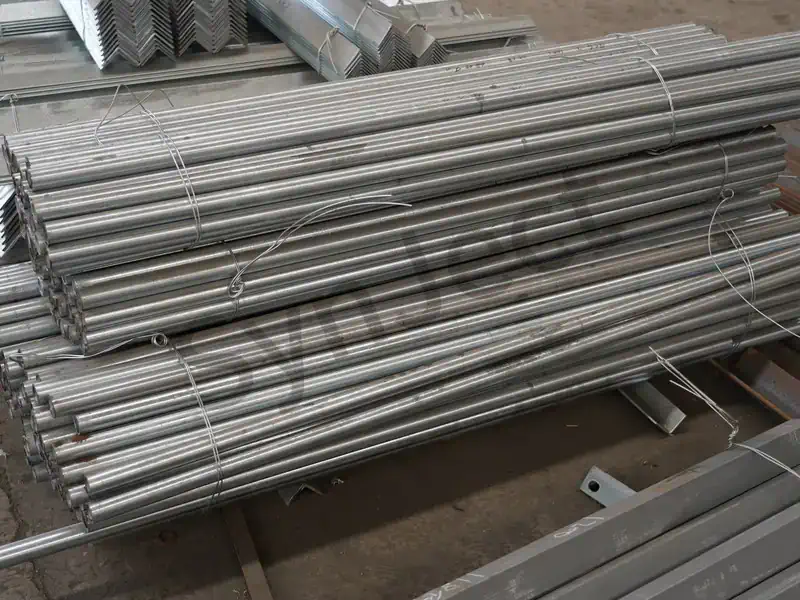
steel purlin spacer tube are short steel tubes placed over round steel sag rods in lightweight steel structures. Together with the sag rods, they form struts used in areas subjected to both tension and compression (such as roof ridges, eaves, and steep-sloped roofs). steel purlin spacer tube are generally made of Q235 welded steel pipes or galvanized steel pipes, with common diameters of φ32×2.0~2.5, and lengths equal to the purlin spacing. steel purlin spacer tube convert the sag rod system from a tension-only system into a two-force member capable of bearing compression, ensuring the geometric invariability of the roof.
Technical Specifications
| Parameter | Specification |
|---|---|
| Common Specifications | φ32×2.0~2.5 |
| Material | Q235 welded steel pipe or galvanized steel pipe |
| Length | Equal to purlin spacing (approx. 0.5~1.5m) |
| Installation Position | Roof ridges, eaves, and sag rod locations requiring compression resistance |
| Relationship with Sag Rod | Sleeved over the round steel sag rod, with both ends pressed tightly against the purlins |
| Connection Method | Sag rod passes through the sleeve, locked by nuts at both ends |
| Anti-corrosion Treatment | Hot-dip galvanizing or anti-rust paint |
| Function | Enables the sag rod system to bear both tension and compression |
| Accessories | Round steel sag rod, diagonal sag rod |
| Execution Standard | GB 51022 |
Values are the range we fabricate routinely. Project-specific sizes, grades and coating systems are confirmed on the approved shop drawing before release to production.
Advantages vs Engineering Considerations
| Advantages | Engineering Considerations |
|---|---|
| Simple structure: Ordinary steel pipe slipped over the sag rod, low cost. | Exact length required: Too long cannot fit tightly, too short leaves a gap; requires on-site measurement. |
| Enables sag rods to bear compression: Solves the issue of round steel sag rods not bearing compression, forming stable struts. | Both ends must press tightly: After installation, both ends must tightly fit the purlin webs without gaps. |
| Convenient installation: Installed synchronously with sag rods, no extra welding needed. | Rust risk: Thin pipe walls require galvanizing for anti-corrosion. |
| Standardized: Specifications match purlin spacing, easy selection. | Gap with sag rod: The inner diameter of the sleeve should be 2~4mm larger than the sag rod for easy insertion. |
| Improves overall roof stiffness: Forms a geometric invariable system together with sag rods and diagonal sag rods. | Cannot replace diagonal sag rods: Sleeve struts still need to cooperate with diagonal sag rods to form a complete system. |
Frequently Asked Questions
What is a steel purlin spacer tube?
A short steel purlin spacer tube over a round steel sag rod, turning the sag rod system into a strut that can bear compression.
What specifications are used for steel purlin spacer tube?
Commonly φ32×2.0~2.5 galvanized steel pipes.
How do steel purlin spacer tube and sag rods work together?
The sag rod passes through the sleeve; the sleeve ends press tightly against purlin webs, and sag rod ends are locked with nuts.
Where are steel purlin spacer tube used?
Ridges, eaves, and other areas subjected to both tension and compression.
What is the length of the sleeve?
Equal to the purlin spacing, generally 0.5~1.5m.
Can it work without a sleeve?
No, ordinary round steel sag rods can only bear tension; compression zones must have sleeve struts.
How to do anti-corrosion for steel purlin spacer tube?
Hot-dip galvanizing is preferred, or anti-rust paint.
Do the ends of the sleeve need to be welded?
No, the sag rod nuts lock tightly to make the sleeve press tight.
What is the relationship between steel purlin spacer tube and diagonal sag rods?
At the ridge, diagonal sag rods + sleeve struts form a triangular stable unit.
Can a sleeve act directly as a purlin?
No, steel purlin spacer tube only serve as struts and do not bear roof loads.
Steel Truss Steel Gutters
Steel Gutters are metal trench components arranged at the edges of plant and building roofs to collect and discharge rainwater, usually set along the eaves or as internal valley Steel Gutters, connecting to downspouts via scuppers. By material, they can be divided into galvanized steel gutters, stainless steel gutters (201/304), and color-coated steel gutters; by layout, into external gutters (hung outside eaves) and internal gutters (embedded within the roof). Gutter design must consider catchment area, rainfall intensity, bottom slope, and scupper sizes to ensure no overflow, backflow, or leakage during rainstorms.
Technical Specifications
| Parameter | Specification |
|---|---|
| Common Materials | Galvanized steel, Stainless steel 304/316, Color-coated steel sheet |
| Plate Thickness | mm ~ 4.0mm |
| Section Forms | Rectangular, trapezoidal, curved |
| Common Dimensions | Width 300~1200mm, Depth 150~800mm |
| Slope | Gutter bottom longitudinal slope ≥0.5% (sloping towards scupper) |
| Scupper Spacing | m (calculated based on rainfall volume) |
| Connection | Welded or seamed, overlap ≥100mm |
| Anti-corrosion | Stainless steel needs no anti-corrosion; galvanized/color steel maintained per environment |
| Accessories | Scuppers, downspouts, gutter brackets, end caps |
| Execution Standard | GB 50015 "Standard for design of building water supply and drainage", GB 51022 |
Values are the range we fabricate routinely. Project-specific sizes, grades and coating systems are confirmed on the approved shop drawing before release to production.
Advantages vs Engineering Considerations
| Advantages | Engineering Considerations |
|---|---|
| Organized drainage: Prevents rainwater from randomly washing over walls and foundations. | Welds prone to leakage: Poor on-site welding leads to leaks; requires full welding and water tightness tests. |
| Corrosion-resistant materials: Stainless steel gutters can be used in humid and corrosive environments. | Cold regions need freeze protection: Internal gutters in cold areas require insulation to prevent freezing. |
| Factory prefabrication: Manufactured in segments, assembled on-site, fast construction. | Blockage risks: Leaves and dust easily block scuppers; requires regular cleaning. |
| Neat appearance: Metal gutters coordinate aesthetically with building facades. | Corrosive environments demand specific materials: Chemical/coastal areas must use 316 stainless steel or thickened galvanization. |
| Customizable: Cross-section dimensions and forms customized per architectural and drainage needs. | Thermal expansion must be considered: Long gutters need expansion joints or sliding brackets. |
Frequently Asked Questions
What materials are used for Steel Gutters?
Commonly galvanized steel sheet, stainless steel 304/316, color-coated steel sheet.
How thick are gutter plates?
Generally 1.0~4.0mm; large-span Steel Gutters use thick plates or additional gutter brackets.
What is the difference between external and internal Steel Gutters?
External Steel Gutters are hung outside eaves; internal Steel Gutters are embedded inside the roof, flanked by roof surfaces.
What is the gutter slope?
The longitudinal bottom slope is generally ≥0.5%, sloping towards the scupper.
What is the scupper spacing?
Generally ≤30m or one per bay, calculated by local rainfall intensity and catchment area.
How are gutter welds treated?
Water tightness tests are conducted after full welding, followed by exterior anti-corrosion or waterproof coatings.
How to do anti-corrosion for Steel Gutters?
Stainless steel is exempt; galvanized sheets get topcoats; chemical zones use 316 stainless steel.
What should be noted for Steel Gutters in cold regions?
Internal Steel Gutters need insulation to prevent frost heaving cracks and frozen scuppers.
How is gutter expansion handled?
Lengths exceeding 30m require expansion joints or one end with a sliding bracket.
How to repair leaking Steel Gutters?
Clean welds, re-weld, apply waterproof coating, or replace plate segments if necessary.
Steel Truss Eave Strut Purlin
Technical Specifications
| Parameter | Specification |
|---|---|
| Common Sections | Circular tube φ89×3~φ159×6, H-beam, round steel |
| Material | Q235B, Q355B |
| Classification | Rigid tie rod (compression), Flexible tie rod (tension) |
| Layout Position | Roof truss ends, ridges, column tops, corners |
| Connection Method | Bolted to the connection plate at the rigid frame end |
| Function | Transfers longitudinal horizontal forces, reduces effective length of compressive members |
| Spacing | Corresponds to bracing bays, generally every alternate bay |
| Accessories | Forms a spatial system together with horizontal bracing and column bracing |
| Anti-corrosion | Galvanized or painted |
| Execution Standard | GB 50017, GB 51022 |
Values are the range we fabricate routinely. Project-specific sizes, grades and coating systems are confirmed on the approved shop drawing before release to production.
Advantages vs Engineering Considerations
| Advantages | Engineering Considerations |
|---|---|
| Forms spatial stability system: Eave Strut Purlin + bracing make the plant a geometrically invariable spatial structure. | Rigid Eave Strut Purlin have larger sections: Compressive Eave Strut Purlin must control slenderness ratios, needing larger sections than tension members. |
| Reduces compressive effective length: Provides lateral fulcrums for rigid frame ends and roof truss end compression members. | Numerous gusset plate welds: End gusset plates require many welds. |
| Flexible layout: Can be adjusted based on roof modeling and doorway positions. | Affects headroom: Ridge and eaves Eave Strut Purlin may occupy a small amount of space. |
| Material saving: Flexible Eave Strut Purlin only require round steel. | Tensioning must be controlled: Flexible round steel Eave Strut Purlin must be tensioned during installation. |
| Convenient installation: Bolted at both ends, fast construction. | Cannot be omitted: Omission leads to a geometrically variable system. |
Frequently Asked Questions
What is Eave Strut Purlin?
A member arranged longitudinally connecting adjacent rigid frames, divided into rigid and flexible Eave Strut Purlin.
What is the difference between rigid and flexible Eave Strut Purlin?
Rigid Eave Strut Purlin can bear compression (circular tubes/H-beams); flexible Eave Strut Purlin only bear tension (round steel/angle steel).
Where are Eave Strut Purlin placed?
Roof truss ends, ridges, column tops, and column base elevations.
What is the relationship between Eave Strut Purlin and column bracing?
Eave Strut Purlin connect adjacent column rows, working with column bracing to form a longitudinal stability system.
What are common cross-sections for Eave Strut Purlin?
Rigid Eave Strut Purlin commonly use circular tubes φ89×4~φ159×6; flexible Eave Strut Purlin use round steel.
How are Eave Strut Purlin connected?
Both ends are bolted to the gusset plates at the rigid frame ends.
Why can't Eave Strut Purlin be omitted?
Omission deprives the rigid frame ends of lateral support, making the system geometrically variable.
Do flexible Eave Strut Purlin need tensioning?
Yes, tensioned using turnbuckles.
What is the difference between Eave Strut Purlin and sag rods?
Eave Strut Purlin run longitudinally connecting rigid frames; sag rods connect purlins to reduce their out-of-plane effective length.
How to do anti-corrosion for Eave Strut Purlin?
Galvanizing or anti-rust paint + topcoat.
Qualification Certificate
Your projects are protected by world-class standards. From CE (EN 1090) to ISO 9001, our qualifications are not just paper—they are the rigorous daily reality on our shop floor.




Have drawings or a BOQ ready?
Related Projects
Projects where this sub-system was detailed, fabricated and shipped as part of the structural package.
SynJect:Scale. Precision. Certainty.
SYNJECT delivers comprehensive steel structure solutions engineered for the global value chain. From investors seeking ROI to engineers demanding exact compliance, we transform complex blueprints into robust realities—on time and without friction.
From Blueprint to Site. Zero Friction.



Detailed Engineering
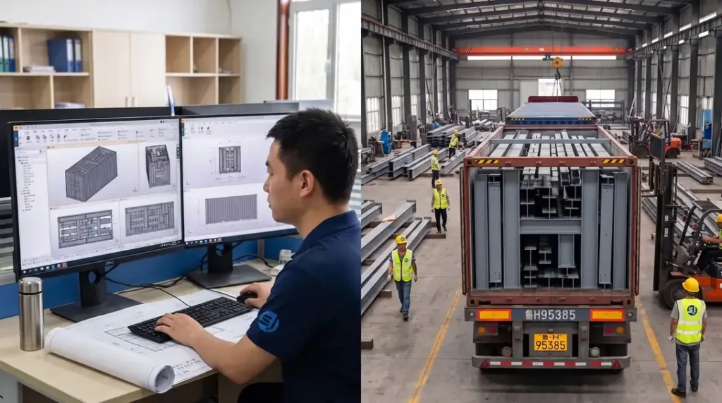
Utilizing advanced BIM platforms such as Tekla Structures, detailed 3D modeling and shop drawings are executed strictly in compliance with AISC 360 or Eurocode 3 (EN 1993). Connection designs are rigorously verified, with manufacturing drawings generated to ISO 2768-m tolerance standards. 100% clash detection with primary architectural and MEP systems is performed to ensure zero structural conflicts during field erection.
Nesting & Material Optimization
Intelligent nesting layouts are performed using advanced software like FastCAM/SigmaNEST in accordance with EN 10029 / ASTM A6 dimensional standards. Accounting for cutting kerf (2mm–5mm depending on plate thickness) and thermal contraction allowances, raw material utilization exceeds 92%. Offcuts are digitally barcode-tracked to ensure 100% mill test report (MTR) traceability.
Raw Material Incoming Inspection
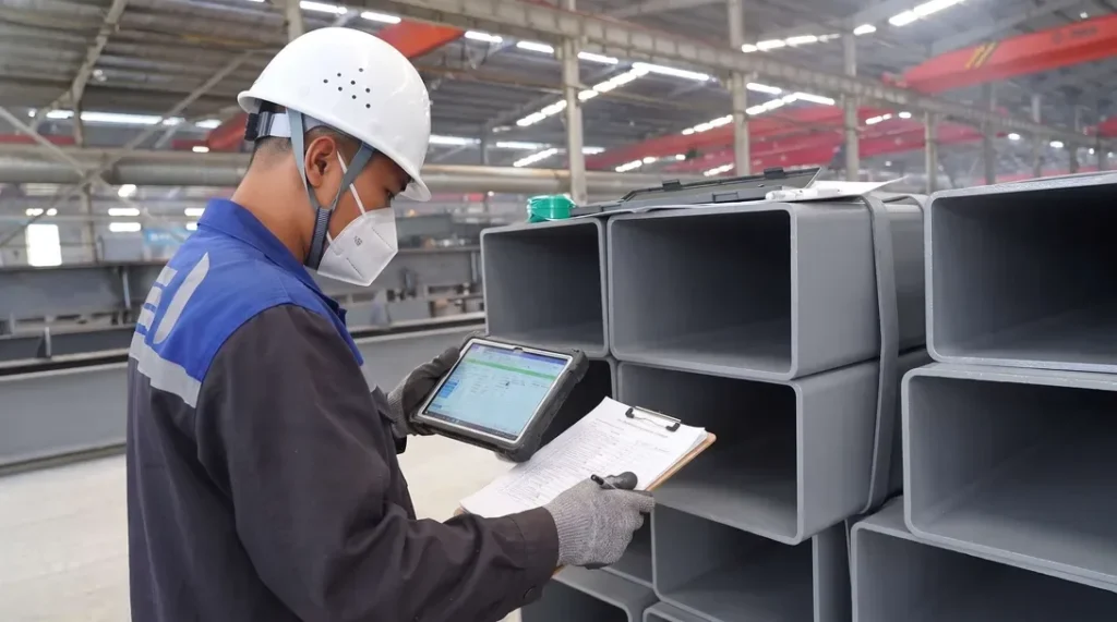
All structural steel (Q355B/C/D, ASTM A572 Gr.50, S355JR/J2) must be accompanied by EN 10204 3.1 Mill Test Reports (MTR). Incoming quality control conducts 100% dimensional and visual inspections under ASTM A6 / EN 10029, verifying thickness tolerances (Class A/B) and internal lamination integrity via Ultrasonic Testing (UT) to ASTM A435. Chemical composition and mechanical properties are spot-verified by accredited 3rd-party labs.
CNC Cutting & Edge Preparation
Plate profiling and component cutting are executed via CNC oxy-fuel, high-definition plasma, and multi-kW fiber laser equipment. Cut surface quality strictly complies with EN ISO 9013 for perpendicularity and surface roughness ±2.5°, Range 3/4 tolerance. Multi-axis CNC beveling machines execute weld prep bevel angles within ±2.5° and root face dimensions within ±1.0 mm.
Weld Distortion Straightening
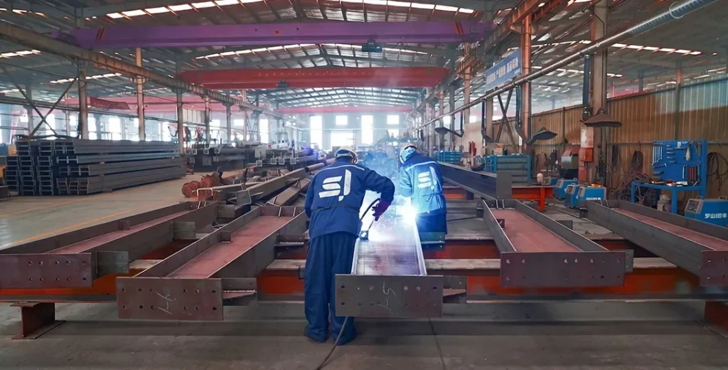
Welding is performed exclusively by AWS D1.1 or EN ISO 9606 certified welders using qualified Welding Procedure Specifications (WPS) supported by Procedure Qualification Records (PQR) per AWS D1.1 / ISO 15614. Submerged Arc Welding (SAW) and Flux-Cored Arc Welding (FCAW) dominate Complete Joint Penetration (CJP) and fillet welds. Heat input is strictly controlled, achieving weld quality levels conforming to ISO 5817 Quality Level B or AWS D1.1 standards.
Non-Destructive Testing (NDT)
Post-weld angular distortion, camber, and sweep are rectified using automated hydraulic flange straighteners and controlled thermal flame straightening. Heating temperatures for High-Strength Low-Alloy (HSLA) steels are strictly maintained between 600℃ - 650℃ (air-cooled, zero water quenching) to prevent microstructural degradation. Post-straightening straightness tolerances meet ±3 mm, conforming to EN 1090-2 Execution Class 2 (EXC2) and AISC COSP standards.
Trial Assembly & Shop Alignment
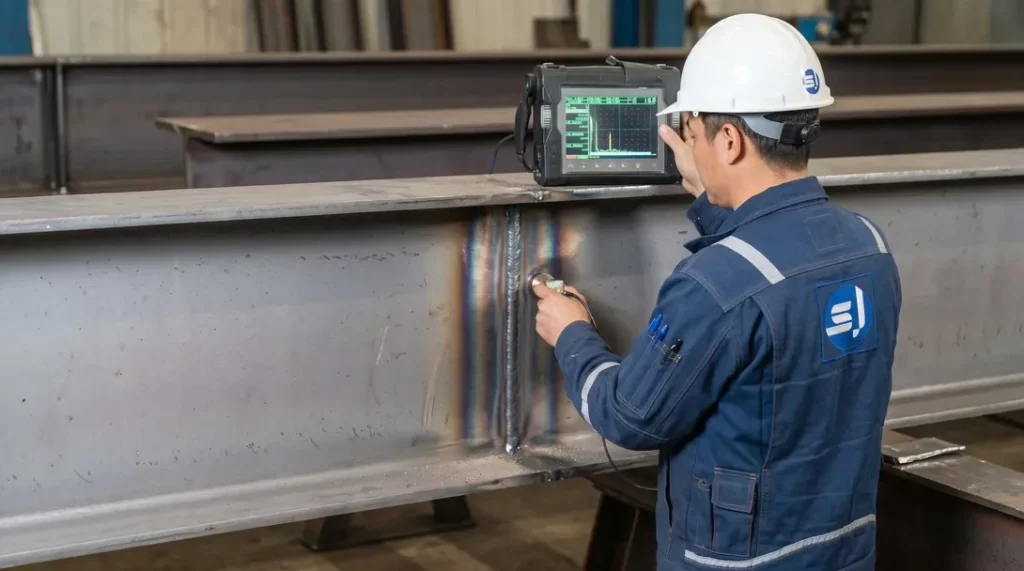
NDT protocols are operated by ISO 9712 / ASNT Level II certified NDT personnel. 100% of critical Complete Joint Penetration (CJP) welds undergo Ultrasonic Testing (UT per ISO 17640 / ASTM E164) or Magnetic Particle Testing (MT per ISO 17638 / ASTM E709). Radiographic Testing (RT) is applied as requested for heavy sections. Weld acceptance conforms strictly to ISO 11666 Acceptance Level 1 or AWS D1.1 criteria.
Surface Preparation & Protective Coating
Complex geometries, long-span trusses, and heavy framing undergo 1:1 physical trial assembly or high-precision 3D laser scanning virtual assembly per EN 1090-2 / AISC requirements. Bolt hole alignment is verified (≥ 95% free-pass rate for high-strength bolts), and critical dimensions (span, camber, 3D spatial alignment) are verified within tight tolerance limits (±2.0 mm) to eliminate site fitting risks.
Measure Paint Film Thickness
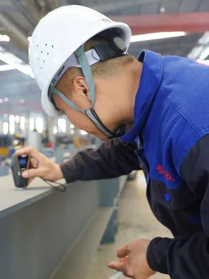
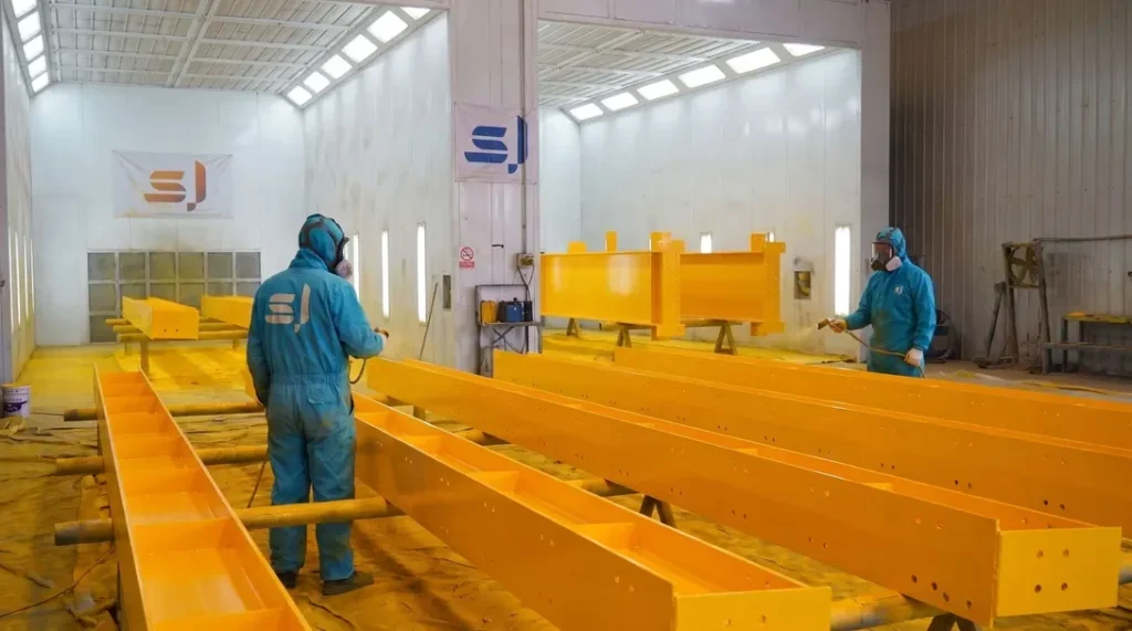
Structural members undergo automated shot blasting to achieve SSPC-SP10 / NACE No. 2 / ISO 8501-1 Sa 2.5 cleanliness, with a surface profile (anchor depth) of 45–75μm. High-performance protective coatings are applied using airless spray technology in compliance with ISO 12944 (C3 to CX corrosive environments), featuring Inorganic/Organic Zinc-Rich Epoxy Primers, Epoxy Micaceous Iron Oxide Intermediate coats, and Polyurethane/Fluorocarbon Topcoats. Dry Film Thickness (DFT) is verified using calibrated magnetic gauges adhering strictly to the 90/10 rule.
Final Quality Inspection & Certification
Final Quality Control (FQC) performs a comprehensive holistic audit, inspecting paint aesthetics (zero runs, pinholes, sagging), critical geometry, bolt hole pitches, and laser/stenciled component mark traceability. A complete Manufacturing Data Report (MDR)—comprising MTRs, NDT records, coating inspection logs, and Certificates of Conformance—is compiled to support CE Marking (DoP under EN 1090) and AISC final acceptance.
Export Packaging & Logistics Protection
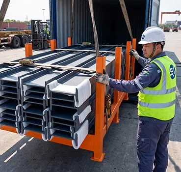
Protective packaging is engineered for containerized (40HQ/OT/FR) and breakbulk ocean freight under heavy maritime transit conditions. Structural members are bundled on heavy-duty steel skids with high-tensile steel strapping. Machined connections and contact surfaces are wrapped with VCI anti-corrosion film, EPE foam padding, and heavy rubber cushions. All timber packing complies fully with ISPM 15 phytosanitary standards and IMO Cargo Stowage and Securing (CSS) rules.
Global Field Erection & Site Management
We deliver international site erection supervision and turnkey EPCM construction services adhering to OSHA 1926 safety protocols, AISC COSP, and EN 1090-2 erection standards. Field teams, led by multilingual HSE and QA/QC engineers, utilize high-precision total stations to maintain structural plumbness within H/1000 (≤25mm max). High-Strength Structural Bolting is executed via calibrated Wrench or Turn-of-Nut methods with 100% torque audit documentation.
Get Your 24-Hour BOQ and Cost Plan
See how much steel tonnage and ocean freight you can save before fabrication begins
Steel Weight Savings
1:1 Tekla 3D modeling optimizes beam-column ratios to eliminate redundant material costs.
Zero-Clash Code Verification
Checked against EN 1090 and local wind/seismic loads.
Engineer-to-Engineer Review
Verified by our lead engineers—Zero pushy sales calls, Just actionable data and factory price.
CE EN 1090-1•ISO 9001•ISO 14001•ISO 45001
Lead Engineers Online
🔒 100% Private and Secure, No Spam