Home / Products / LGS House / Openings & Finish

Openings & Finish

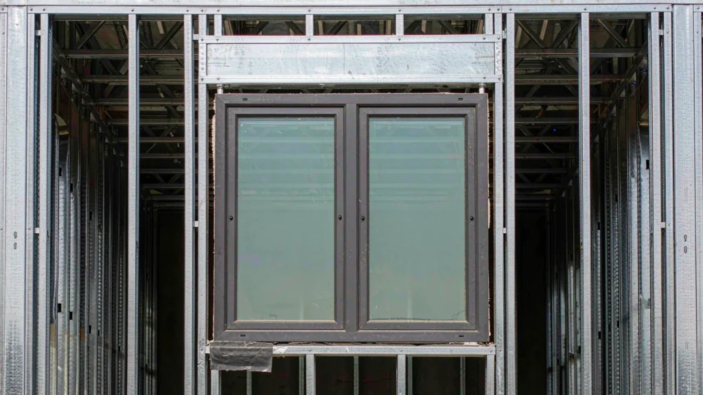
Dark grey aluminium window frame set into a bare galvanized steel stud opening with lintel and sill flashing

Openings are framed and reinforced at the factory rather than cut on site, which keeps the bracing layout intact. Ceiling and flooring are supplied to match the service layout.

What we fabricate in this sub-system

  • Doors & Windows
  • Ceiling & Flooring
Dark grey aluminium window with double glazing set into a light gauge steel stud opening with sill flashing

Doors & Windows

Openings are where an LGS house is most often compromised after handover: a window cut in later, a lintel that was not fitted, or a door that drags because the frame moved. The principle is simple — openings are formed and reinforced in the factory, not cut on site.

Technical Specifications

Parameter Specification
Frame Material Aluminium thermal-break or UPVC with steel insert
Glazing Double tempered insulated, Low-E option
U-Value 1.4–1.8 W/(m²·K) typical for the frame+glass assembly
Wind Load ASTM E330 / EN 12210, class per project
Water Tightness ASTM E331 / EN 12208
Air Leakage ASTM E283 / EN 12207, Class 4 typical
Opening Types Casement, sliding, fixed, tilt-turn
Fixing Screwed through frame to steel studs, sealed with flashing tape
Reinforcement Lintel and jack studs factory-fitted
Standard EN 14351-1 / local code

Dimensions and grades shown are the range we fabricate routinely. Final values are confirmed on the approved shop drawing before release to production.

Advantages vs Engineering Considerations

Advantages Engineering Considerations
Factory-formed openings keep the bracing intact Cutting an opening on site usually means cutting the strap bracing. Factory openings are designed with the bracing rerouted around them.
Thermal-break frames matter on steel walls Aluminium conducts; a thermal break between the outer and inner profile prevents the frame becoming a cold bridge and condensing indoors.
Flashing tape, not sealant The weather seal at an opening is a taped membrane integrated with the wall's water barrier. A bead of mastic around the frame will fail within a few seasons.

Frequently Asked Questions

Can windows be added after the house is built?

Yes, but the opening must be engineered — lintel, jack studs and bracing rerouted. Cutting a hole in a braced wall panel without that work compromises the structure.

Double tempered insulated glass, with a Low-E coating where solar gain or heat loss matters. The specification follows the local energy code.

With a flashing tape system integrated with the wall's water-resistive barrier, plus backer rod and sealant at the internal air barrier. Not with external mastic alone.

If the frame has no thermal break, yes. The cold aluminium surface drops below dew point and water runs down the glass — which is why thermal-break profiles are specified.

Laminated or toughened glass and multi-point locking, specified to the project. On ground-floor openings in some markets the glazing class is code-mandated.

Gypsum board ceiling on galvanized C-section channels with hanger rods, seen from below during installation

Ceiling & Flooring

Ceiling and flooring are the finishes the buyer actually touches, and on an LGS house they also carry acoustic and fire performance. The detail that decides satisfaction is not the board — it is what happens at the perimeter, where the ceiling meets a steel frame that moves and conducts.

Technical Specifications

Parameter Specification
Ceiling Gypsum board on resilient channel, or suspended grid
Flooring Structural plywood, cement board, or steel deck with topping
Acoustic Ceiling Resilient channel plus mineral wool above
Fire Rating Board type and layers per code, typically 30–60 min
Perimeter Detail Movement gap with acoustic sealant at steel frame
Screws Self-drilling, countersunk, corrosion-protected
Finish Skim coat and paint, or direct-fix panels
Underlay Acoustic underlay under hard flooring
Tolerance Ceiling level ± 3 mm over 3 m
Standard EN 520 for gypsum board, local fire code

Dimensions and grades shown are the range we fabricate routinely. Final values are confirmed on the approved shop drawing before release to production.

Advantages vs Engineering Considerations

Advantages Engineering Considerations
Resilient channel does the acoustic work Fixing board directly to steel studs transmits impact noise. A resilient channel decouples it, which is the difference between a quiet room and a drum.
Perimeter gap is a fire and acoustic detail The gap between board and frame is sealed with acoustic intumescent sealant, not filled with plaster. Skipping it leaks both sound and smoke.
Steel deck needs the right underlay Hard flooring directly on steel deck sounds hollow. A structural topping or acoustic underlay resolves it at modest cost.

Frequently Asked Questions

How is impact noise reduced on a steel floor?

By decoupling and adding mass: a structural topping or acoustic underlay, plus a resilient ceiling below. It is much easier to design in than to fix afterwards.

Typically 30–60 minutes with one or two layers of fire-rated board on the steel frame. The rating and the board specification come from the local code.

Because the steel frame moves thermally and the board is rigid. A movement gap with sealant absorbs it; a tight butt joint cracks.

Yes, on a rigid deck with a suitable substrate and flexible adhesive. Direct tiling onto a flexible timber deck without a decoupling layer usually cracks.

Not always. A direct-fixed ceiling on resilient channel is common in houses; a suspended grid is used where services need access above.

Qualification Certificate

Your projects are protected by world-class standards. From CE (EN 1090) to ISO 9001, our qualifications are not just paper—they are the rigorous daily reality on our shop floor.

AISCCEOTCInternational Welder
ISO 9001 Quality Management System

Have drawings or a BOQ ready?

SynJect
SynJect factory
SynJect factory
SynJect factory
Kunlun Lu
SynJect factory
SynJect factory
SynJect factory
SynJect factory
SynJect factory

SynJect:Scale. Precision. Certainty.

SYNJECT delivers comprehensive steel structure solutions engineered for the global value chain. From investors seeking ROI to engineers demanding exact compliance, we transform complex blueprints into robust realities—on time and without friction.

From Blueprint to Site. Zero Friction.

Detailed Engineering & Shop Drawing DevelopmentNesting & Material OptimizationRaw Material Incoming InspectionCNC Cutting & Edge PreparationWeld Distortion StraighteningNon-Destructive Testing (NDT)Trial Assembly & Shop AlignmentSurface Preparation & Protective CoatingMeasure Paint Film ThicknessFinal Quality Inspection & CertificationExport Packaging & Logistics ProtectionGlobal Field Erection & Site Management
Stage.01

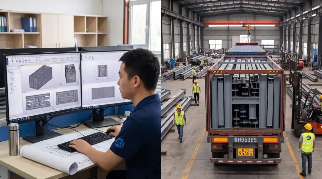
Detailed Engineering

Utilizing advanced BIM platforms such as Tekla Structures, detailed 3D modeling and shop drawings are executed strictly in compliance with AISC 360 or Eurocode 3 (EN 1993). Connection designs are rigorously verified, with manufacturing drawings generated to ISO 2768-m tolerance standards. 100% clash detection with primary architectural and MEP systems is performed to ensure zero structural conflicts during field erection.

STANDARDAISC 360 / EN 1993
METRIC VALUETolerance ±0.01mm
Stage.02

Nesting & Material Optimization

Intelligent nesting layouts are performed using advanced software like FastCAM/SigmaNEST in accordance with EN 10029 / ASTM A6 dimensional standards. Accounting for cutting kerf (2mm–5mm depending on plate thickness) and thermal contraction allowances, raw material utilization exceeds 92%. Offcuts are digitally barcode-tracked to ensure 100% mill test report (MTR) traceability.

STANDARDEN 10029 / ASTM A6
METRIC VALUEUtilization 95%
Stage.03

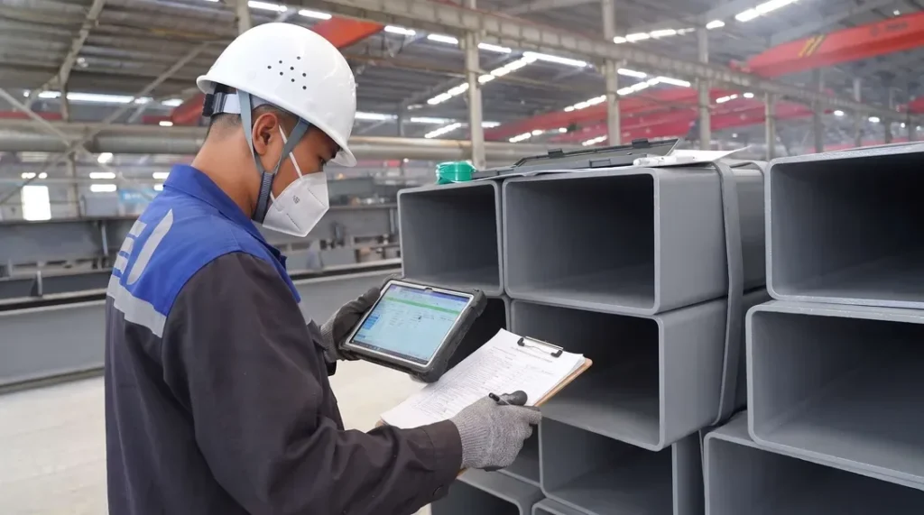
Raw Material Incoming Inspection

All structural steel (Q355B/C/D, ASTM A572 Gr.50, S355JR/J2) must be accompanied by EN 10204 3.1 Mill Test Reports (MTR). Incoming quality control conducts 100% dimensional and visual inspections under ASTM A6 / EN 10029, verifying thickness tolerances (Class A/B) and internal lamination integrity via Ultrasonic Testing (UT) to ASTM A435. Chemical composition and mechanical properties are spot-verified by accredited 3rd-party labs.

STANDARDEN 10204 3.1 / ASTM A435
METRIC VALUEClass A/B and ASTM A435
Stage.04

CNC Cutting & Edge Preparation

Plate profiling and component cutting are executed via CNC oxy-fuel, high-definition plasma, and multi-kW fiber laser equipment. Cut surface quality strictly complies with EN ISO 9013 for perpendicularity and surface roughness ±2.5°, Range 3/4 tolerance. Multi-axis CNC beveling machines execute weld prep bevel angles within ±2.5° and root face dimensions within ±1.0 mm.

STANDARDEN ISO 9013
METRIC VALUERa ≤12.5μm
Stage.05

Weld Distortion Straightening

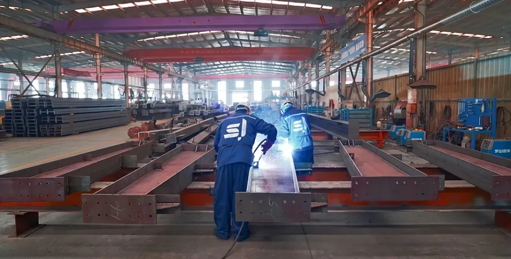
Welding is performed exclusively by AWS D1.1 or EN ISO 9606 certified welders using qualified Welding Procedure Specifications (WPS) supported by Procedure Qualification Records (PQR) per AWS D1.1 / ISO 15614. Submerged Arc Welding (SAW) and Flux-Cored Arc Welding (FCAW) dominate Complete Joint Penetration (CJP) and fillet welds. Heat input is strictly controlled, achieving weld quality levels conforming to ISO 5817 Quality Level B or AWS D1.1 standards.

STANDARDAWS D1.1 / EN ISO 9606
METRIC VALUEISO 5817Level B
Stage.06

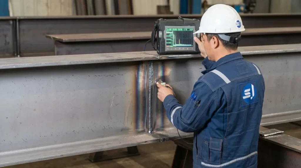
Non-Destructive Testing (NDT)

Post-weld angular distortion, camber, and sweep are rectified using automated hydraulic flange straighteners and controlled thermal flame straightening. Heating temperatures for High-Strength Low-Alloy (HSLA) steels are strictly maintained between 600℃ - 650℃ (air-cooled, zero water quenching) to prevent microstructural degradation. Post-straightening straightness tolerances meet ±3 mm, conforming to EN 1090-2 Execution Class 2 (EXC2) and AISC COSP standards.

STANDARDEN 1090-2 EXC2 / AISC COSP
METRIC VALUETolerances ±3 mm
Stage.07

Trial Assembly & Shop Alignment

NDT protocols are operated by ISO 9712 / ASNT Level II certified NDT personnel. 100% of critical Complete Joint Penetration (CJP) welds undergo Ultrasonic Testing (UT per ISO 17640 / ASTM E164) or Magnetic Particle Testing (MT per ISO 17638 / ASTM E709). Radiographic Testing (RT) is applied as requested for heavy sections. Weld acceptance conforms strictly to ISO 11666 Acceptance Level 1 or AWS D1.1 criteria.

STANDARDISO 11666 Level 1 / AWS D1.1
METRIC VALUE100% UT
Stage.08

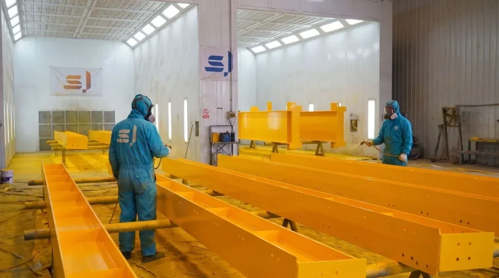
Surface Preparation & Protective Coating

Complex geometries, long-span trusses, and heavy framing undergo 1:1 physical trial assembly or high-precision 3D laser scanning virtual assembly per EN 1090-2 / AISC requirements. Bolt hole alignment is verified (≥ 95% free-pass rate for high-strength bolts), and critical dimensions (span, camber, 3D spatial alignment) are verified within tight tolerance limits (±2.0 mm) to eliminate site fitting risks.

STANDARDAISC / EN 1090-2
METRIC VALUETolerance ±2.0 mm
Stage.09

Measure Paint Film Thickness

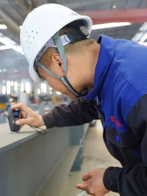
Structural members undergo automated shot blasting to achieve SSPC-SP10 / NACE No. 2 / ISO 8501-1 Sa 2.5 cleanliness, with a surface profile (anchor depth) of 45–75μm. High-performance protective coatings are applied using airless spray technology in compliance with ISO 12944 (C3 to CX corrosive environments), featuring Inorganic/Organic Zinc-Rich Epoxy Primers, Epoxy Micaceous Iron Oxide Intermediate coats, and Polyurethane/Fluorocarbon Topcoats. Dry Film Thickness (DFT) is verified using calibrated magnetic gauges adhering strictly to the 90/10 rule.

STANDARDISO 8501-1 Sa 2.5 / ISO 12944
METRIC VALUE45 - 75μm
Stage.10

Final Quality Inspection & Certification

Final Quality Control (FQC) performs a comprehensive holistic audit, inspecting paint aesthetics (zero runs, pinholes, sagging), critical geometry, bolt hole pitches, and laser/stenciled component mark traceability. A complete Manufacturing Data Report (MDR)—comprising MTRs, NDT records, coating inspection logs, and Certificates of Conformance—is compiled to support CE Marking (DoP under EN 1090) and AISC final acceptance.

STANDARDEN 1090 / AISC
METRIC VALUEQA/QC Final Release
Stage.11

Export Packaging & Logistics Protection

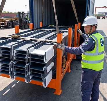
Protective packaging is engineered for containerized (40HQ/OT/FR) and breakbulk ocean freight under heavy maritime transit conditions. Structural members are bundled on heavy-duty steel skids with high-tensile steel strapping. Machined connections and contact surfaces are wrapped with VCI anti-corrosion film, EPE foam padding, and heavy rubber cushions. All timber packing complies fully with ISPM 15 phytosanitary standards and IMO Cargo Stowage and Securing (CSS) rules.

STANDARDISPM 15 / IMO CSS
METRIC VALUE40HQ/OT/FR
Stage.12

Global Field Erection & Site Management

We deliver international site erection supervision and turnkey EPCM construction services adhering to OSHA 1926 safety protocols, AISC COSP, and EN 1090-2 erection standards. Field teams, led by multilingual HSE and QA/QC engineers, utilize high-precision total stations to maintain structural plumbness within H/1000 (≤25mm max). High-Strength Structural Bolting is executed via calibrated Wrench or Turn-of-Nut methods with 100% torque audit documentation.

STANDARDOSHA 1926 / EN 1090-2
METRIC VALUE≤ H/1000

Get Your 24-Hour BOQ and Cost Plan

See how much steel tonnage and ocean freight you can save before fabrication begins

8–15%

Steel Weight Savings

1:1 Tekla 3D modeling optimizes beam-column ratios to eliminate redundant material costs.

0.0mm

Zero-Clash Code Verification

Checked against EN 1090 and local wind/seismic loads.

100%

Engineer-to-Engineer Review

Verified by our lead engineers—Zero pushy sales calls, Just actionable data and factory price.

CE EN 1090-1•ISO 9001•ISO 14001•ISO 45001

Engineering & Inquiry Desk

Lead Engineers Online

Drawings
Drawings

🔒 100% Private and Secure, No Spam