Home / Products / Steel Bridge Structures / Deck & Accessories
Deck & Accessories
Deck, railing and drainage complete the structure and carry the traffic surface. These items are usually specified alongside the girders so the interfaces are resolved in one drawing set.
What we fabricate in this sub-system
- Deck System
- Railings
- Drainage
Deck System
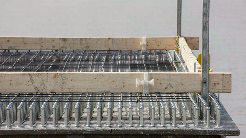
The deck system is what the traffic actually touches: an orthotropic steel plate, a concrete slab on shear studs, or a precast panel. Each has a different interface with the girders, a different weight, and a different construction sequence. The choice usually comes down to span, weight limit and how much site work the location can tolerate.
Technical Specifications
| Parameter | Specification |
|---|---|
| Types | Orthotropic steel deck, composite concrete slab, precast panel |
| Steel Deck Plate | 12–20 mm typical |
| Concrete Slab | 200–300 mm on shear studs |
| Shear Connection | Headed studs to AWS D1.1 |
| Waterproofing | Spray-applied membrane or sheet system |
| Wearing Course | Asphalt 60–80 mm typical |
| Drainage Falls | 1.5–2.5% to gully, set at deck level |
| Expansion Joint Interface | Deck edge beam cast or welded to joint |
| Coating | Steel deck: C4–C5-M underside, membrane on top |
| Construction | Sequence agreed with girder erection method |
Dimensions and grades shown are the range we fabricate routinely. Final values are confirmed on the approved shop drawing before release to production.
Advantages vs Engineering Considerations
| Advantages | Engineering Considerations |
|---|---|
| Composite slab adds stiffness and mass | A concrete slab on studs raises the neutral axis and damps vibration, but it also adds dead load that the girders must be designed for from the start. |
| Orthotropic deck saves weight | A steel plate deck cuts self-weight dramatically on long spans, at the cost of far more welding and a fatigue-sensitive rib-to-deck detail. |
| Waterproofing is the whole game | Most deck deterioration starts at the waterproofing, not the structure. The membrane, its upstands and the joint interface decide how long the deck lasts. |
Frequently Asked Questions
Composite slab or orthotropic steel deck?
Composite concrete is the default for road bridges up to long spans — cheaper, heavier, quieter. Orthotropic steel decks are used where weight governs, such as long-span or movable bridges, and cost much more to fabricate.
How is the deck connected to the girders?
Through headed shear studs welded to the top flange for composite decks, or by direct welding for orthotropic decks. In both cases the connection detail drives the fatigue life.
What waterproofing do you specify?
A spray-applied or sheet membrane under the asphalt, carried up at kerbs, joints and drainage outlets. The upstand details matter more than the membrane itself.
How are drainage falls achieved?
Either by cambering the girders or by a varying thickness overlay. Setting falls in the overlay is cheaper but adds dead load; cambering is set at design stage.
Can the deck be precast?
Yes, precast panels on studs speed up site work and reduce wet trades, but the panel-to-panel joints and the shear pockets need careful grouting to develop composite action.
Railings
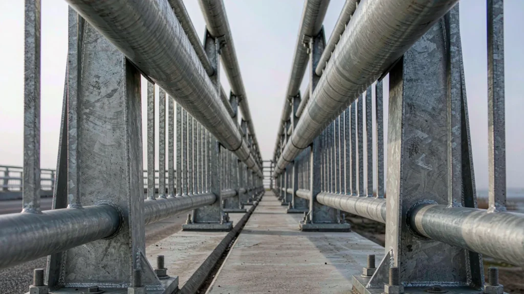
Bridge railings are a vehicle restraint system and a pedestrian barrier, and they are usually specified by performance rather than by shape. The structural question is the anchor: a railing that passes a crash test on a test rig can still tear out of a deck if the anchor detail was not designed for the actual edge condition.
Technical Specifications
| Parameter | Specification |
|---|---|
| Types | Vehicle parapet, pedestrian handrail, combined |
| Performance | Crash-tested to EN 1317 / AASHTO MASH where required |
| Post Spacing | 1.5–2.5 m typical |
| Post Section | H-section, RHS or proprietary profile |
| Material | S355JR, S275JR, or aluminium alloy |
| Anchor | Cast-in or post-fixed anchors to deck edge |
| Height | 1.1 m typical for pedestrian, per code for vehicle |
| Coating | Hot-dip galvanizing ≥ 65 μm, or duplex system |
| Infill | Horizontal rails, vertical bars or mesh |
| Standard | EN 1317 / AASHTO LRFD, local road authority spec |
Dimensions and grades shown are the range we fabricate routinely. Final values are confirmed on the approved shop drawing before release to production.
Advantages vs Engineering Considerations
| Advantages | Engineering Considerations |
|---|---|
| Performance-specified, not shape-specified | Buying on crash test class rather than appearance is the only defensible route; a railing that looks substantial may not restrain a vehicle. |
| Galvanizing is the default for a reason | Railings are thin, exposed and hard to repaint. Hot-dip galvanizing gives a maintenance-free life that paint cannot match at this section thickness. |
| The anchor detail governs the outcome | Posts transfer load into the deck edge, which is often the thinnest and most congested part of the slab. The anchor design has to match the edge reinforcement. |
Frequently Asked Questions
Does the railing need crash testing?
If it is a vehicle restraint system on a public road, yes — to EN 1317 or AASHTO MASH depending on the market, and the class has to match the road category. Pedestrian-only handrails are covered by building or bridge codes instead.
How is the railing fixed to the deck?
By cast-in anchors set before the deck is poured, or post-fixed anchors into the hardened edge. Cast-in is preferred because the edge is congested and post-fixing risks hitting reinforcement.
What coating should be used?
Hot-dip galvanizing of at least 65 μm is standard. In coastal or de-icing salt exposure a duplex system — galvanizing plus paint — is used, and stainless is specified for the fixings.
Can the railing be replaced?
Yes, and it should be designed to be. Bolted base plates with accessible fixings allow replacement after an impact without breaking out the deck edge.
How is the pedestrian handrail height set?
By the local code, typically 1.1 m on bridges, with the infill gap sized to prevent a child passing through. Where the railing also restrains vehicles, the higher performance requirement governs the geometry.
Drainage
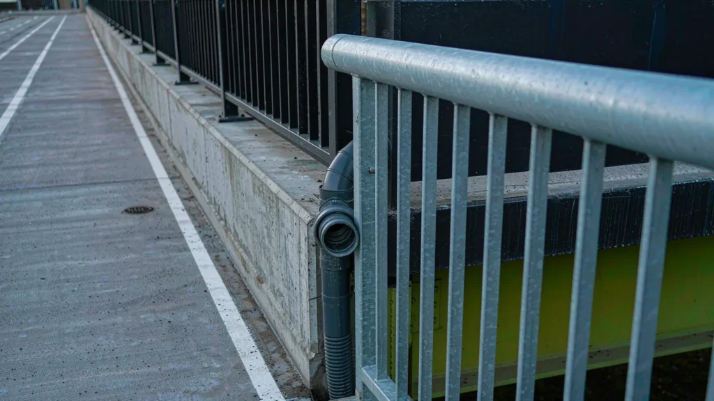
Bridge drainage looks like a minor item until water starts running over the edge and down the girder, or a blocked gully freezes and splits its pipe. The design question is where the water goes and how it is kept out of the bearings and the deck waterproofing — which means the outlets, the pipe route and the maintenance access all have to be decided together.
Technical Specifications
| Parameter | Specification |
|---|---|
| Components | Gully, scupper, downpipe, drainage trough, outlet |
| Gully Spacing | 10–20 m typical, at low points |
| Pipe Material | HDPE, uPVC or stainless steel |
| Diameter | 100–200 mm typical |
| Fixing | Bracketed to girder web or soffit, with expansion allowance |
| Access | Rodding eyes and removable gratings |
| Freeze Protection | Slope and drain-down detail; no standing water |
| Coating | Galvanized brackets, stainless fixings |
| Discharge | To drainage system or vegetated outfall, not onto the substructure |
| Standard | Local highway drainage spec / EN 1991-1-4 for wind on pipes |
Dimensions and grades shown are the range we fabricate routinely. Final values are confirmed on the approved shop drawing before release to production.
Advantages vs Engineering Considerations
| Advantages | Engineering Considerations |
|---|---|
| Keeps water off the bearings | Discharging clear of the bearings and the abutment is the whole point; a pipe that ends above the bearing shelf is worse than no pipe at all. |
| Accessible for rodding | Gullies block. Rodding eyes at each change of direction and removable gratings turn a blockage into a ten-minute job instead of a scaffold. |
| Expansion allowance in the pipe run | The bridge moves and the pipe is fixed to it; without slip joints or loops the pipe pulls out of its sockets within a few seasons. |
Frequently Asked Questions
Where should bridge deck water discharge?
Into a piped system that carries it clear of the bearings, abutment and embankment, or to a designed outfall. Discharging over the edge is common and is the main cause of stained girders and corroded bearings.
How often do gullies need cleaning?
At least twice a year, and after leaf fall. The design should make this possible without scaffolding — rodding eyes and accessible gratings are the cheapest maintenance decision on the bridge.
What pipe material is used?
HDPE or uPVC for most runs, stainless steel where the pipe is exposed or the environment is aggressive. Brackets are galvanized and fixings stainless to avoid galvanic corrosion.
How is thermal movement accommodated?
With slip joints, loops or flexible couplings at intervals along the run. The pipe is fixed to a structure that moves tens of millimetres, so a rigid run will fail at the joints.
Can drainage be omitted on a short bridge?
Sometimes, where the deck falls directly to the approaches and the waterproofing is carried over the edge. It still has to be a designed detail — water running down the girder end is not drainage.
Qualification Certificate
Your projects are protected by world-class standards. From CE (EN 1090) to ISO 9001, our qualifications are not just paper—they are the rigorous daily reality on our shop floor.



Have drawings or a BOQ ready?
Related Projects
Projects where this sub-system was detailed, fabricated and shipped as part of the structural package.
SynJect:Scale. Precision. Certainty.
SYNJECT delivers comprehensive steel structure solutions engineered for the global value chain. From investors seeking ROI to engineers demanding exact compliance, we transform complex blueprints into robust realities—on time and without friction.
From Blueprint to Site. Zero Friction.



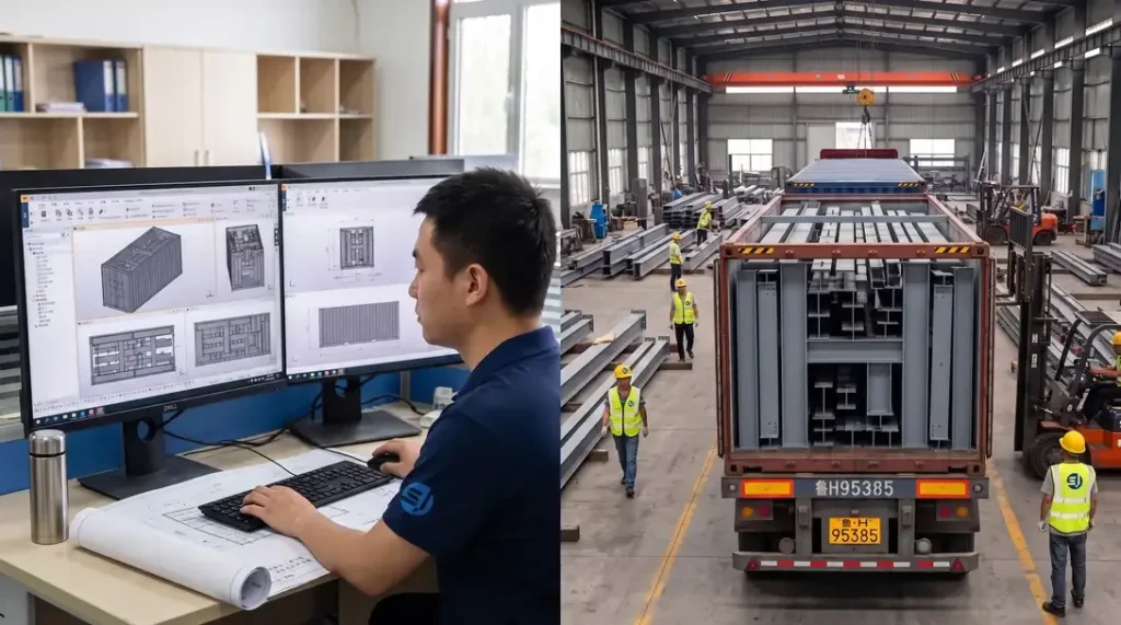
Detailed Engineering
Utilizing advanced BIM platforms such as Tekla Structures, detailed 3D modeling and shop drawings are executed strictly in compliance with AISC 360 or Eurocode 3 (EN 1993). Connection designs are rigorously verified, with manufacturing drawings generated to ISO 2768-m tolerance standards. 100% clash detection with primary architectural and MEP systems is performed to ensure zero structural conflicts during field erection.
Nesting & Material Optimization
Intelligent nesting layouts are performed using advanced software like FastCAM/SigmaNEST in accordance with EN 10029 / ASTM A6 dimensional standards. Accounting for cutting kerf (2mm–5mm depending on plate thickness) and thermal contraction allowances, raw material utilization exceeds 92%. Offcuts are digitally barcode-tracked to ensure 100% mill test report (MTR) traceability.
Raw Material Incoming Inspection
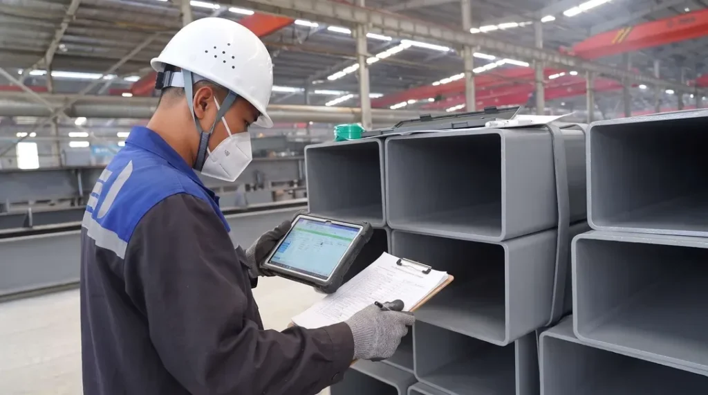
All structural steel (Q355B/C/D, ASTM A572 Gr.50, S355JR/J2) must be accompanied by EN 10204 3.1 Mill Test Reports (MTR). Incoming quality control conducts 100% dimensional and visual inspections under ASTM A6 / EN 10029, verifying thickness tolerances (Class A/B) and internal lamination integrity via Ultrasonic Testing (UT) to ASTM A435. Chemical composition and mechanical properties are spot-verified by accredited 3rd-party labs.
CNC Cutting & Edge Preparation
Plate profiling and component cutting are executed via CNC oxy-fuel, high-definition plasma, and multi-kW fiber laser equipment. Cut surface quality strictly complies with EN ISO 9013 for perpendicularity and surface roughness ±2.5°, Range 3/4 tolerance. Multi-axis CNC beveling machines execute weld prep bevel angles within ±2.5° and root face dimensions within ±1.0 mm.
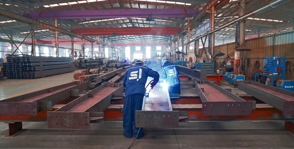
Weld Distortion Straightening
Welding is performed exclusively by AWS D1.1 or EN ISO 9606 certified welders using qualified Welding Procedure Specifications (WPS) supported by Procedure Qualification Records (PQR) per AWS D1.1 / ISO 15614. Submerged Arc Welding (SAW) and Flux-Cored Arc Welding (FCAW) dominate Complete Joint Penetration (CJP) and fillet welds. Heat input is strictly controlled, achieving weld quality levels conforming to ISO 5817 Quality Level B or AWS D1.1 standards.
Non-Destructive Testing (NDT)
Post-weld angular distortion, camber, and sweep are rectified using automated hydraulic flange straighteners and controlled thermal flame straightening. Heating temperatures for High-Strength Low-Alloy (HSLA) steels are strictly maintained between 600℃ - 650℃ (air-cooled, zero water quenching) to prevent microstructural degradation. Post-straightening straightness tolerances meet ±3 mm, conforming to EN 1090-2 Execution Class 2 (EXC2) and AISC COSP standards.
Trial Assembly & Shop Alignment
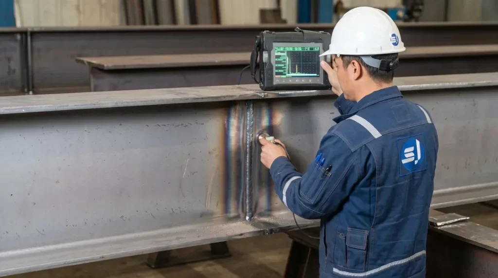
NDT protocols are operated by ISO 9712 / ASNT Level II certified NDT personnel. 100% of critical Complete Joint Penetration (CJP) welds undergo Ultrasonic Testing (UT per ISO 17640 / ASTM E164) or Magnetic Particle Testing (MT per ISO 17638 / ASTM E709). Radiographic Testing (RT) is applied as requested for heavy sections. Weld acceptance conforms strictly to ISO 11666 Acceptance Level 1 or AWS D1.1 criteria.
Surface Preparation & Protective Coating
Complex geometries, long-span trusses, and heavy framing undergo 1:1 physical trial assembly or high-precision 3D laser scanning virtual assembly per EN 1090-2 / AISC requirements. Bolt hole alignment is verified (≥ 95% free-pass rate for high-strength bolts), and critical dimensions (span, camber, 3D spatial alignment) are verified within tight tolerance limits (±2.0 mm) to eliminate site fitting risks.
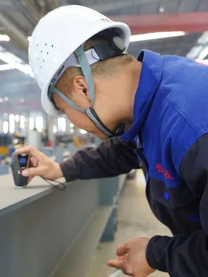
Measure Paint Film Thickness
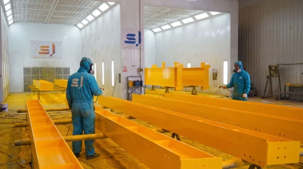
Structural members undergo automated shot blasting to achieve SSPC-SP10 / NACE No. 2 / ISO 8501-1 Sa 2.5 cleanliness, with a surface profile (anchor depth) of 45–75μm. High-performance protective coatings are applied using airless spray technology in compliance with ISO 12944 (C3 to CX corrosive environments), featuring Inorganic/Organic Zinc-Rich Epoxy Primers, Epoxy Micaceous Iron Oxide Intermediate coats, and Polyurethane/Fluorocarbon Topcoats. Dry Film Thickness (DFT) is verified using calibrated magnetic gauges adhering strictly to the 90/10 rule.
Final Quality Inspection & Certification
Final Quality Control (FQC) performs a comprehensive holistic audit, inspecting paint aesthetics (zero runs, pinholes, sagging), critical geometry, bolt hole pitches, and laser/stenciled component mark traceability. A complete Manufacturing Data Report (MDR)—comprising MTRs, NDT records, coating inspection logs, and Certificates of Conformance—is compiled to support CE Marking (DoP under EN 1090) and AISC final acceptance.
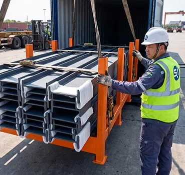
Export Packaging & Logistics Protection
Protective packaging is engineered for containerized (40HQ/OT/FR) and breakbulk ocean freight under heavy maritime transit conditions. Structural members are bundled on heavy-duty steel skids with high-tensile steel strapping. Machined connections and contact surfaces are wrapped with VCI anti-corrosion film, EPE foam padding, and heavy rubber cushions. All timber packing complies fully with ISPM 15 phytosanitary standards and IMO Cargo Stowage and Securing (CSS) rules.
Global Field Erection & Site Management
We deliver international site erection supervision and turnkey EPCM construction services adhering to OSHA 1926 safety protocols, AISC COSP, and EN 1090-2 erection standards. Field teams, led by multilingual HSE and QA/QC engineers, utilize high-precision total stations to maintain structural plumbness within H/1000 (≤25mm max). High-Strength Structural Bolting is executed via calibrated Wrench or Turn-of-Nut methods with 100% torque audit documentation.
Get Your 24-Hour BOQ and Cost Plan
See how much steel tonnage and ocean freight you can save before fabrication begins
Steel Weight Savings
1:1 Tekla 3D modeling optimizes beam-column ratios to eliminate redundant material costs.
Zero-Clash Code Verification
Checked against EN 1090 and local wind/seismic loads.
Engineer-to-Engineer Review
Verified by our lead engineers—Zero pushy sales calls, Just actionable data and factory price.
CE EN 1090-1•ISO 9001•ISO 14001•ISO 45001
Lead Engineers Online
🔒 100% Private and Secure, No Spam