Home / Products / Space Frame Structure / Foundation Anchor Bolts

Foundation Anchor Bolts

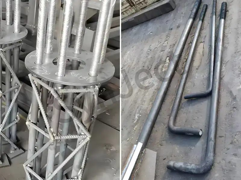
Anchor bolts and high-strength bolts forming the foundation anchor bolts of a space frame structure
Hot-dip galvanised anchor bolt assemblies with setting templates supplied for a space frame structure

Space Frame Anchor Bolts

Anchor bolts (foundation bolts) are key connection components between steel column bases and concrete foundations. They withstand vertical tension, shear force, and bending moments transmitted from the column base, ensuring the upper structure is firmly anchored to the foundation. By form, they include J-type, L-type, U-type, anchor plate type, and straight rod type; common materials include Q235B, Q355B, Q390B, and Grade 45 high-quality carbon steel. By anchoring method, they are divided into cast-in-place anchor bolts and post-installed anchors (chemical anchors, expansion anchors). Anchor bolt diameters are typically M24~M64, with quantity and layout determined by column base internal force calculations. Pre-embedding positioning accuracy directly affects steel column installation quality.

Technical Specifications

Parameter Specification
Common Forms J-type, L-type, U-type, anchor plate type, straight rod type
Common Specifications M24, M27, M30, M33, M36, M42, M45, M48, M52, M56, M60, M64
Material Q235B, Q355B, Q390B, Grade 45 steel (Property class 4.6/5.6/8.8)
Embedment Depth Determined by tension calculation, generally 20~40 times the diameter
Matching Nuts Double nuts (anti-loosening) or single nut + washer
Positioning Method Using fixing templates for overall pre-embedding to ensure bolt group spacing and elevation
Cover Thickness Concrete cover inside foundation ≥50mm
Grouting Secondary grouting with non-shrink grout under the column base plate
Anti-corrosion Treatment Embedded concrete part is not treated; exposed part is painted
Execution Standard GB 50017, GB 50010, JGJ 145 "Technical specification for post-installed fastenings in concrete structures"

Values are the range we fabricate routinely. Project-specific sizes, grades and coating systems are confirmed on the approved shop drawing before release to production.

Advantages vs Engineering Considerations

Advantages Engineering Considerations
Reliable anchoring: Transfers column base forces through mechanical interlocking and grout bonding force, safe and reliable. High pre-embedding precision required: Large pre-embedding deviations will seriously affect steel column installation; templates are strictly required.
Standardized specifications: Full mature series from M24 to M64, easy selection. Sufficient embedment depth required for tension: Insufficient depth causes pull-out failure; must be anchored per calculation.
Mature positioning technology: Using fixing templates, bolt group precision can be controlled within ±2mm. Exposed parts prone to rust: Requires painting or galvanizing for anti-corrosion, and regular maintenance.
Convenient installation adjustment: Base elevation and horizontal position can be finely adjusted via nuts and backing plates. Shear keys needed for shear force: Pure anchor bolts have limited shear resistance; large shear bases need shear keys.
Post-installed undercut anchors suit retrofits: Adding steel columns to existing structures can use chemical or expansion anchors. Grouting quality is critical: Incompact secondary grouting affects force transmission; non-shrink grout must be used.

Frequently Asked Questions

What are the forms of anchor bolts?

J-type, L-type, U-type, anchor plate, and straight rod types. J-type and anchor plate types are most common.

Determined by column base internal force calculations, commonly M24~M48. Heavy-duty columns may use M56 or above.

Tension anchor embedment is generally 20~40 times the diameter, satisfying concrete anchoring requirements.

Commonly Q235B, Q355B, Q390B, or Grade 45 steel, with property classes 4.6/5.6/8.8.

Using section steel templates to position the bolt group as a whole, tied to the rebar cage before concrete pouring.

Small deviations can be adjusted by enlarging holes and using pad plates; large deviations require a design treatment plan.

The gap between the base plate and foundation top is filled with non-shrink grout to ensure uniform force transmission.

Usually double nuts for anti-loosening, or single nut + spring washer.

Chemical anchors or post-installed mechanical undercut anchors, verified per JGJ 145.

Embedded concrete parts require no treatment; exposed parts are coated with anti-rust paint or galvanized.

EN 14399 and ASTM A325 / A490 structural bolt sets supplied for a space frame structure

Space Frame HSFG Bolts

HSFG bolts connection is one of the primary connection methods for on-site splicing of steel structures. By applying pre-tension to the bolts, a compressive friction force is generated between the connected plates to transmit internal forces. By force mechanism, they are divided into friction-type connections and bearing-type connections; by property class, into Grade 8.8 and Grade 10.9; by shape, into large hex head hsfg bolts and tension control (TC) hsfg bolts (twist-off bolts). Large hex bolts are installed using the torque method, while TC bolts are installed by shearing off the spline (plum blossom head). High-strength bolt connections feature fast construction, controllable quality, and detachability, making them the most common connection form for on-site steel structure installation.

Technical Specifications

Parameter Specification
Property Class Grade 8.8, Grade 10.9
Common Specifications M16, M20, M22, M24, M27, M30
Type Large hex head, Tension Control (TC) type (spline head)
Connection Type Friction-type, Bearing-type
Pre-tension Application Standard pre-tension values specified in GB 50017
Friction Surface Treatment Sandblasting, sandblasting then red rust surface
Slip Coefficient Q235: 0.45, Q355: 0.50 (based on treatment method)
Construction Tools Torque wrench, electric shear wrench
Exposed Threads threads exposed after tightening
Execution Standard GB/T 1228, GB/T 3632, GB 50205

Values are the range we fabricate routinely. Project-specific sizes, grades and coating systems are confirmed on the approved shop drawing before release to production.

Advantages vs Engineering Considerations

Advantages Engineering Considerations
Fast construction speed: On-site bolted assembly without welding, shortens project duration. High requirements for friction surfaces: Connection plates must be sandblasted and kept clean, free of oil or paint.
Controllable quality: Pre-tension and torque can be quantitatively tested, ensuring stable quality. Pre-tension loss needs compensation: Pre-tension relaxes over long-term use; over-tightening and re-tightening are needed during construction.
Detachable: Facilitates structural modification, expansion, and demolition recovery. High hole precision required: Bolt hole misalignment must be strictly controlled; gas cutting to enlarge holes is prohibited.
Reliable stress performance: Friction-type connections transmit force via friction, with no slip and good fatigue resistance. Marking required after final tightening: To prevent missed tightening, paint marking is done post final-tightening.
Low labor intensity: Compared to on-site welding, it improves the working environment. Torque wrenches need regular calibration: Torque values directly affect pre-tension; wrenches must be calibrated regularly.

Frequently Asked Questions

What are the classifications of hsfg bolts?

By property: Grade 8.8 and Grade 10.9; by shape: large hex head and tension control (TC) type.

Friction-type transmits force via friction without slip; bearing-type allows slip, transmitting force through bolt shank and hole wall bearing.

Commonly M20, M22, M24; large-span structures may use M27, M30.

An electric wrench shears off the spline head, immediately achieving the specified pre-tension; construction is simple.

To improve the slip coefficient of the connection plates and ensure frictional force transmission.

Hole diameter is generally 1.5~2.0mm larger than the shank; excess misalignment requires reaming or changing holes.

Generally 2~3 threads exposed.

Codes stipulate hsfg bolts must not be reused; they are scrapped after removal.

Must be regularly calibrated, and verified before and after shifts to ensure accurate torque.

Gas cutting is strictly prohibited; if deviation exceeds limits, a reamer must be used after obtaining design approval.

Qualification Certificate

Your projects are protected by world-class standards. From CE (EN 1090) to ISO 9001, our qualifications are not just paper—they are the rigorous daily reality on our shop floor.


AISCCEOTCInternational Welder
ISO 9001 Quality Management System

Have drawings or a BOQ ready?

SynJect
SynJect factory
SynJect factory
SynJect factory
Kunlun Lu
SynJect factory
SynJect factory
SynJect factory
SynJect factory
SynJect factory

SynJect:Scale. Precision. Certainty.

SYNJECT delivers comprehensive steel structure solutions engineered for the global value chain. From investors seeking ROI to engineers demanding exact compliance, we transform complex blueprints into robust realities—on time and without friction.

From Blueprint to Site. Zero Friction.

Detailed Engineering & Shop Drawing DevelopmentNesting & Material OptimizationRaw Material Incoming InspectionCNC Cutting & Edge PreparationWeld Distortion StraighteningNon-Destructive Testing (NDT)Trial Assembly & Shop AlignmentSurface Preparation & Protective CoatingMeasure Paint Film ThicknessFinal Quality Inspection & CertificationExport Packaging & Logistics ProtectionGlobal Field Erection & Site Management
Stage.01

Detailed Engineering

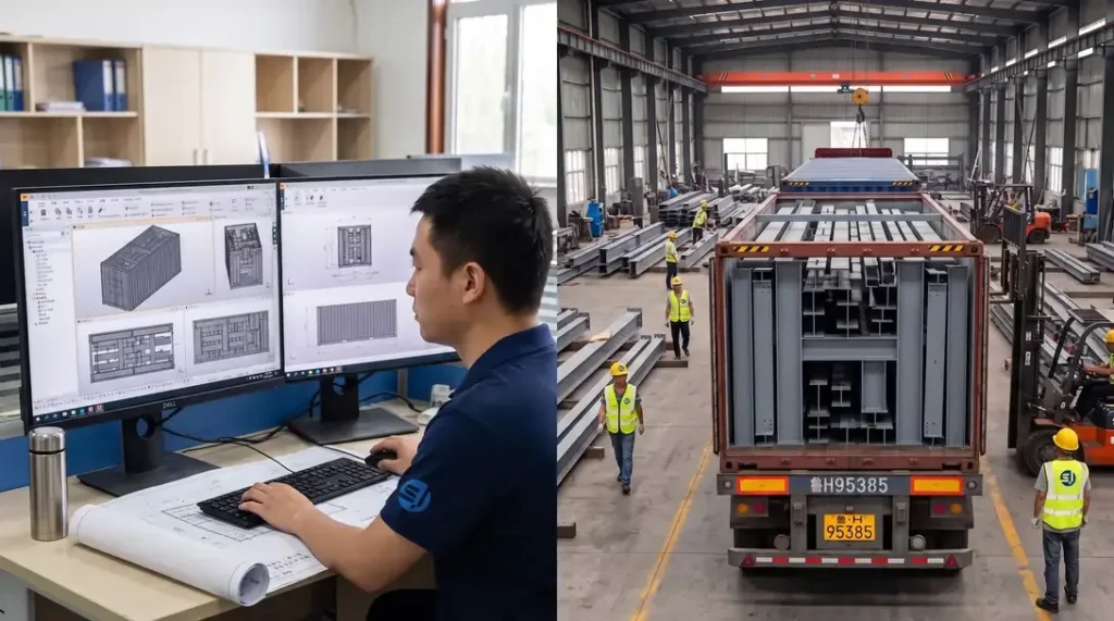
Utilizing advanced BIM platforms such as Tekla Structures, detailed 3D modeling and shop drawings are executed strictly in compliance with AISC 360 or Eurocode 3 (EN 1993). Connection designs are rigorously verified, with manufacturing drawings generated to ISO 2768-m tolerance standards. 100% clash detection with primary architectural and MEP systems is performed to ensure zero structural conflicts during field erection.

STANDARDAISC 360 / EN 1993
METRIC VALUETolerance ±0.01mm
Stage.02

Nesting & Material Optimization

Intelligent nesting layouts are performed using advanced software like FastCAM/SigmaNEST in accordance with EN 10029 / ASTM A6 dimensional standards. Accounting for cutting kerf (2mm–5mm depending on plate thickness) and thermal contraction allowances, raw material utilization exceeds 92%. Offcuts are digitally barcode-tracked to ensure 100% mill test report (MTR) traceability.

STANDARDEN 10029 / ASTM A6
METRIC VALUEUtilization 95%
Stage.03

Raw Material Incoming Inspection

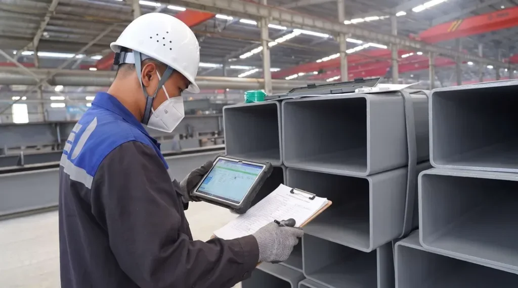
All structural steel (Q355B/C/D, ASTM A572 Gr.50, S355JR/J2) must be accompanied by EN 10204 3.1 Mill Test Reports (MTR). Incoming quality control conducts 100% dimensional and visual inspections under ASTM A6 / EN 10029, verifying thickness tolerances (Class A/B) and internal lamination integrity via Ultrasonic Testing (UT) to ASTM A435. Chemical composition and mechanical properties are spot-verified by accredited 3rd-party labs.

STANDARDEN 10204 3.1 / ASTM A435
METRIC VALUEClass A/B and ASTM A435
Stage.04

CNC Cutting & Edge Preparation

Plate profiling and component cutting are executed via CNC oxy-fuel, high-definition plasma, and multi-kW fiber laser equipment. Cut surface quality strictly complies with EN ISO 9013 for perpendicularity and surface roughness ±2.5°, Range 3/4 tolerance. Multi-axis CNC beveling machines execute weld prep bevel angles within ±2.5° and root face dimensions within ±1.0 mm.

STANDARDEN ISO 9013
METRIC VALUERa ≤12.5μm
Stage.05

Weld Distortion Straightening

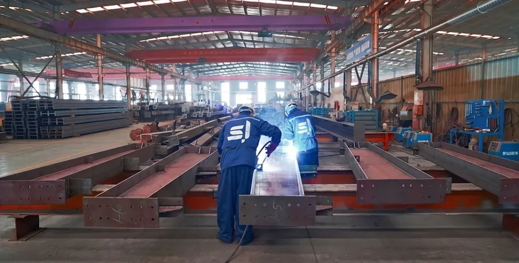
Welding is performed exclusively by AWS D1.1 or EN ISO 9606 certified welders using qualified Welding Procedure Specifications (WPS) supported by Procedure Qualification Records (PQR) per AWS D1.1 / ISO 15614. Submerged Arc Welding (SAW) and Flux-Cored Arc Welding (FCAW) dominate Complete Joint Penetration (CJP) and fillet welds. Heat input is strictly controlled, achieving weld quality levels conforming to ISO 5817 Quality Level B or AWS D1.1 standards.

STANDARDAWS D1.1 / EN ISO 9606
METRIC VALUEISO 5817Level B
Stage.06

Non-Destructive Testing (NDT)

Post-weld angular distortion, camber, and sweep are rectified using automated hydraulic flange straighteners and controlled thermal flame straightening. Heating temperatures for High-Strength Low-Alloy (HSLA) steels are strictly maintained between 600℃ - 650℃ (air-cooled, zero water quenching) to prevent microstructural degradation. Post-straightening straightness tolerances meet ±3 mm, conforming to EN 1090-2 Execution Class 2 (EXC2) and AISC COSP standards.

STANDARDEN 1090-2 EXC2 / AISC COSP
METRIC VALUETolerances ±3 mm
Stage.07

Trial Assembly & Shop Alignment

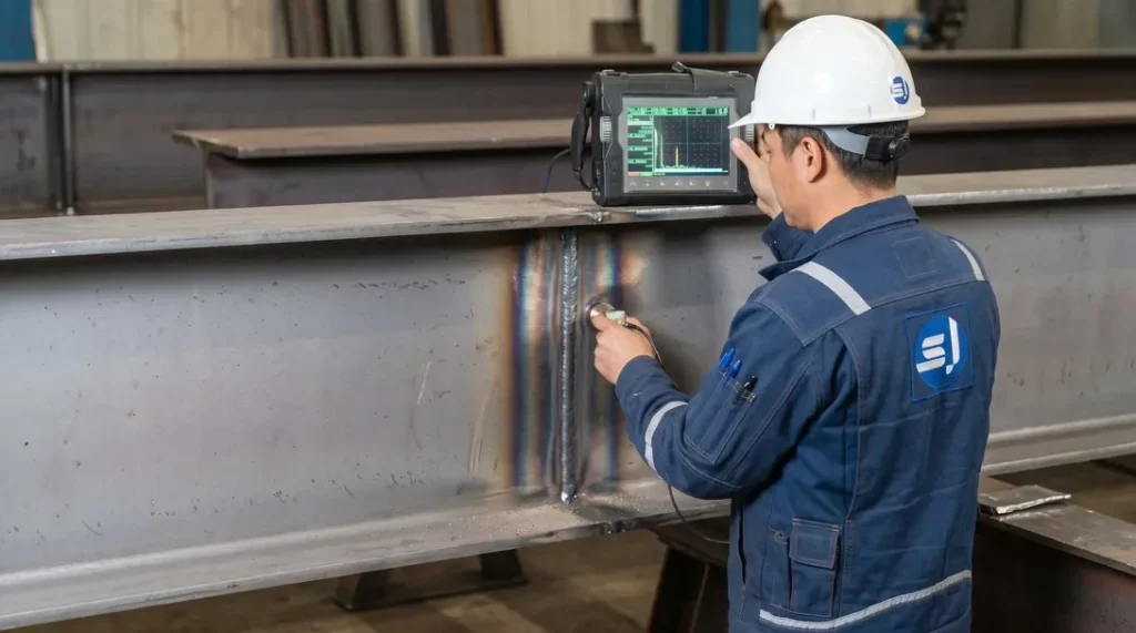
NDT protocols are operated by ISO 9712 / ASNT Level II certified NDT personnel. 100% of critical Complete Joint Penetration (CJP) welds undergo Ultrasonic Testing (UT per ISO 17640 / ASTM E164) or Magnetic Particle Testing (MT per ISO 17638 / ASTM E709). Radiographic Testing (RT) is applied as requested for heavy sections. Weld acceptance conforms strictly to ISO 11666 Acceptance Level 1 or AWS D1.1 criteria.

STANDARDISO 11666 Level 1 / AWS D1.1
METRIC VALUE100% UT
Stage.08

Surface Preparation & Protective Coating

Complex geometries, long-span trusses, and heavy framing undergo 1:1 physical trial assembly or high-precision 3D laser scanning virtual assembly per EN 1090-2 / AISC requirements. Bolt hole alignment is verified (≥ 95% free-pass rate for high-strength bolts), and critical dimensions (span, camber, 3D spatial alignment) are verified within tight tolerance limits (±2.0 mm) to eliminate site fitting risks.

STANDARDAISC / EN 1090-2
METRIC VALUETolerance ±2.0 mm
Stage.09

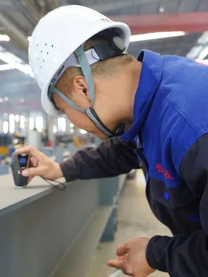
Measure Paint Film Thickness

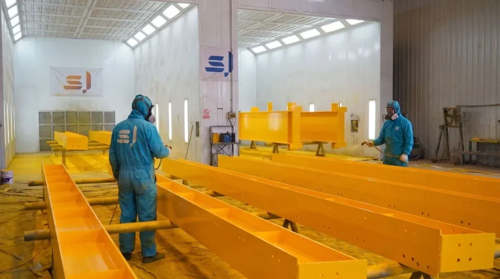
Structural members undergo automated shot blasting to achieve SSPC-SP10 / NACE No. 2 / ISO 8501-1 Sa 2.5 cleanliness, with a surface profile (anchor depth) of 45–75μm. High-performance protective coatings are applied using airless spray technology in compliance with ISO 12944 (C3 to CX corrosive environments), featuring Inorganic/Organic Zinc-Rich Epoxy Primers, Epoxy Micaceous Iron Oxide Intermediate coats, and Polyurethane/Fluorocarbon Topcoats. Dry Film Thickness (DFT) is verified using calibrated magnetic gauges adhering strictly to the 90/10 rule.

STANDARDISO 8501-1 Sa 2.5 / ISO 12944
METRIC VALUE45 - 75μm
Stage.10

Final Quality Inspection & Certification

Final Quality Control (FQC) performs a comprehensive holistic audit, inspecting paint aesthetics (zero runs, pinholes, sagging), critical geometry, bolt hole pitches, and laser/stenciled component mark traceability. A complete Manufacturing Data Report (MDR)—comprising MTRs, NDT records, coating inspection logs, and Certificates of Conformance—is compiled to support CE Marking (DoP under EN 1090) and AISC final acceptance.

STANDARDEN 1090 / AISC
METRIC VALUEQA/QC Final Release
Stage.11

Export Packaging & Logistics Protection

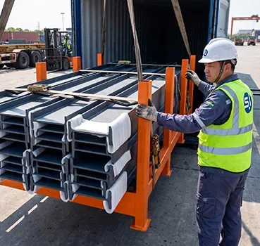
Protective packaging is engineered for containerized (40HQ/OT/FR) and breakbulk ocean freight under heavy maritime transit conditions. Structural members are bundled on heavy-duty steel skids with high-tensile steel strapping. Machined connections and contact surfaces are wrapped with VCI anti-corrosion film, EPE foam padding, and heavy rubber cushions. All timber packing complies fully with ISPM 15 phytosanitary standards and IMO Cargo Stowage and Securing (CSS) rules.

STANDARDISPM 15 / IMO CSS
METRIC VALUE40HQ/OT/FR
Stage.12

Global Field Erection & Site Management

We deliver international site erection supervision and turnkey EPCM construction services adhering to OSHA 1926 safety protocols, AISC COSP, and EN 1090-2 erection standards. Field teams, led by multilingual HSE and QA/QC engineers, utilize high-precision total stations to maintain structural plumbness within H/1000 (≤25mm max). High-Strength Structural Bolting is executed via calibrated Wrench or Turn-of-Nut methods with 100% torque audit documentation.

STANDARDOSHA 1926 / EN 1090-2
METRIC VALUE≤ H/1000

Get Your 24-Hour BOQ and Cost Plan

See how much steel tonnage and ocean freight you can save before fabrication begins

8–15%

Steel Weight Savings

1:1 Tekla 3D modeling optimizes beam-column ratios to eliminate redundant material costs.

0.0mm

Zero-Clash Code Verification

Checked against EN 1090 and local wind/seismic loads.

100%

Engineer-to-Engineer Review

Verified by our lead engineers—Zero pushy sales calls, Just actionable data and factory price.

CE EN 1090-1•ISO 9001•ISO 14001•ISO 45001

Engineering & Inquiry Desk

Lead Engineers Online

Drawings
Drawings

🔒 100% Private and Secure, No Spam