Home / Solutions / Public Buildings / Grand Theater & Performing Arts Center

Iconic Steel Theater Building Solutions

Monumental Spans.

Bridge the gap between architectural ambition and acoustic perfection. We specialize in engineering and manufacturing free-form steel structures for world-class theaters and performing arts centers.Whether it is a drama theater, opera house, concert hall or performing arts center, the structural design must coordinate with the auditorium layout, stage opening, fly tower, scenery-handling systems, lighting and audio equipment, acoustic assemblies and backstage spaces. The structure above the stage may need to support not only roof loads but also rigging systems, lighting trusses, scenery and technical walkways. Auditorium framing must also accommodate sightlines, clear heights and acoustic requirements.

Industry Challenges & Solutions

The challenge in theater engineering is not simply achieving a long span. It is ensuring that stage rigging, scenery movement, audience sightlines, acoustic isolation and building services work together within the same space. Structural planning should start with the actual performance format and equipment requirements rather than leaving interface issues until after the main structure is complete.

THE CHALLENGE

The stage area may contain motorized battens, scenery suspension points, lighting trusses, loudspeakers, projection equipment and technical walkways. Their load locations, concentrations, operating conditions and maintenance requirements vary. A structure designed only for conventional roof loads may not meet the local capacity, deflection or operational requirements of stage equipment.

SynJect ENGINEERED SOLUTION

Before structural design, we collect equipment layouts, suspension loads, support reactions, operating conditions and maintenance requirements from the stage-machinery supplier. Main trusses, secondary beams, rigging beams and connections are designed for the actual loads, with concentrated forces, relevant dynamic effects and structural deflection checked. Any provisions for future equipment must have defined limits and load capacities.

THE CHALLENGE

Theaters and concert halls are sensitive to background noise, reverberation and sound transmission between spaces. Adjacent rehearsal rooms, plant rooms, traffic noise sources or other performance spaces may transmit noise through structural members, floors, walls and building services. If the structure and acoustic assemblies are not coordinated early, acoustic finishes alone may not resolve all structure-borne noise and vibration issues.

SynJect ENGINEERED SOLUTION

We coordinate the structural interfaces for sound-isolating walls, floating floors, suspended ceilings, vibration-isolation bearings and equipment foundations according to the acoustic consultant's performance targets. For spaces requiring a box-in-box arrangement, we define the isolated inner frame, vibration-isolation supports and restrictions on connections to adjacent structures. Acoustic targets and isolation systems are designed by the relevant specialists, while the steel team coordinates the agreed support and connection interfaces.

THE CHALLENGE

To cool 2,000 spectators silently, the HVAC air ducts must be incredibly large so the air moves slowly without "hissing." Standard steel beams block these massive ducts, forcing the mechanical engineers to lower the ceiling. This reduces the acoustic volume of the hall, destroying the natural reverberation needed for opera.

SynJect ENGINEERED SOLUTION

We utilize customized Cellular Beams We precut massive geometric holes through the steel webs based on the MEP layout. This allows the oversized, low-velocity acoustic air ducts to pass directly through the structural framework, preserving the soaring ceiling heights essential for world-class architectural acoustics.

THE CHALLENGE

Star architects design iconic Performing Arts Centers with sweeping organic curves, "liquid" metal shells, and massive overhanging canopies. Executing these free-form, non-linear geometries with traditional concrete is practically impossible, and standard steel fabrication will result in terrifying budget overruns and ugly weld joints.

SynJect ENGINEERED SOLUTION

We specialize in Free-Form Steel Structures and Cast Steel Nodes Using parametric 3D modeling and CNC pipe bending machine for pipe bending + 5-axis CNC cutting/intersection line machining, distinguishing between pipe bending and cutting processes. we translate wild renderings into exact mathematical grids. For complex junctions where 6+ curved pipes meet, we pour custom Cast Steel Nodes, turning the most ambitious structural sculptures into a safe, budget-controlled reality.

THE CHALLENGE

Theater projects may include long-span roof trusses, balcony ring beams, fly-tower steelwork and complex transfer members. Some projects require erection within existing buildings, restricted sites or enclosed structures. If component segmentation, transport dimensions, lifting sequences and connection tolerances are not adequately planned, site assembly, structural alignment and subsequent finishes may be affected.

SynJect ENGINEERED SOLUTION

We use coordinated 3D detailing, fabrication capabilities, transport restrictions and site lifting conditions to plan fabrication and erection. Large components are segmented appropriately, with site splice details, temporary-stability measures and survey requirements defined. Dimensions, welds, high-strength bolted connections and erection positions are checked in accordance with the project quality plan, with agreed inspection records provided at handover.

Technical Specifications

Theater structural parameters must be established in coordination with theater type, audience capacity, scenery systems, suspended equipment, acoustic design and architectural layout. The following values are intended for preliminary discussions and option comparisons, not as universal construction specifications.

Parameter Category Reference Range Typical Reference Value
Customization Available
Individual Building Area 2,000โ€“30,000+ mยฒ 8,000 mยฒ
Building levels 1โ€“6 levels 3 levels
Main auditorium span 15โ€“35 m; larger for major venues 24 m
Large-span auditorium 30โ€“50 m+; project-specific project-specific
Auditorium clear height 8โ€“18 m 12 m
Proscenium opening width 10โ€“20 m; venue-specific 14 m
Fly tower height Approx. 20โ€“35 m or higher; where a fly system is required Based on scenery height and travel
Structural Steel S355 / ASTM A572 Gr.50 / or locally approved grades S355
Structural System Steel frame / transfer structures / Truss/space frame or hybrid systems Project-specific
Grid structure Designed around battens, pulleys, hoists and maintenance systems Stage-equipment drawings
Rigging-support beams Designed for suspension reactions, concentrated loads and load combinations Equipment load schedule
Scenery battens Based on quantity, spacing, travel and working loads Stage machinery design
Balcony and overhang structure Based on seating geometry, support conditions, deflection and sightlines Structural scheme
Stage floor loading Based on scenery, performance equipment, movable platforms and intended use Stage design and local codes
Acoustic separation lines Confirm with acoustic consultants and avoid uncoordinated rigid connections Acoustic design
Wind, snow and seismic actions Calculated to local codes and site conditions Project-specific
Steel fire protection Based on occupancy, fire-resistance requirements and local codes Approved fire-protection design
Corrosivity category Assessed from indoor/outdoor exposure, humidity, pollution and coastal conditions C2โ€“C3
Surface preparation Based on coating system and project specification Sa 2ยฝ / Sa 2ยฝ where specified
Design Codes EN / AISC / GB / AS / Local Codes Location Standards

NoteRoof geometry, suspended equipment and grandstand interfaces shall be confirmed against the final event or operational layout.

Theater Steel Structure Project Process

Theater projects involve structural engineering, architecture, acoustics, stage machinery and MEP systems. A coordinated processโ€”from pre-construction structural and equipment-interface planning through fabrication and erection to final inspection and handoverโ€”helps address component transport, lifting, connections and equipment-installation requirements early.

PHASE 01 / PRE-CONSTRUCTION

Multi-Disciplinary BIM Resolution

We coordinate our LOD 400 digital twin directly with the stage machinery provider and the acoustician's exact HVAC and panel layouts, resolving all spatial conflicts virtually.

PHASE 02 / CONSTRUCTION

Fabrication, Quality Inspection and Site Erection

Steel beams, trusses, tower members and connections are fabricated to approved detailing drawings. Specified dimensional, welding, bolting, surface-treatment and inspection requirements are followed, with transportation and lifting organized around the erection sequence.

PHASE 03 / COMPLETION

Completion & Handover

After steel erection, relevant quality records are compiled in accordance with the contract and project requirements. Critical equipment supports, reserved interfaces, maintenance access and conditions for follow-on specialist work are checked with the project team during handover.

Qualification Certificate

Your projects are protected by world-class standards. From CE (EN 1090) to ISO 9001, our qualifications are not just paperโ€”they are the rigorous daily reality on our shop floor.

AISCCEOTCInternational Welder
ISO 9001 Quality Management System

Recommended Product Systems

Space Frame Structure

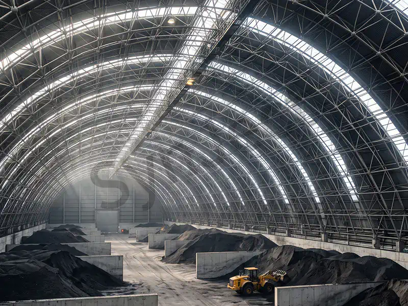
SynJect Space Frame structures provide exceptional 3D stability for large-span architectural designs.

Steel Truss

SynJect Steel Truss systems deliver unparalleled heavy load-bearing capacity and clear-span flexibility.

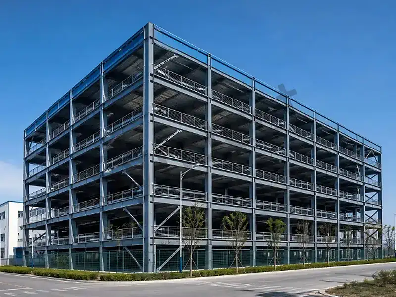
Six-storey multi-storey steel building with exposed steel columns and beams

SynJect Multi-Storey Steel Buildings maximize spatial efficiency and structural integrity for industrial&commercial hubs.

Frequently Asked Questions

The architect designed a free-form outer shell. Can you actually manufacture this shape in steel?

Absolutely. We specialize in parametric free-form architecture. Using CNC pipe bending machine for pipe bending + 5-axis CNC cutting/intersection line machining, distinguishing between pipe bending and cutting processes, we can curve massive steel tubes into complex, liquid-like organic geometries. For the bizarre intersecting joints (where 6 or more curved pipes meet), we manufacture custom solid "Cast Steel Nodes". This ensures the architect's wild vision is not only beautiful but structurally invincible and cost-effective.

We block it at the very foundation. We integrate heavy-duty Elastomeric Bearing Pads between our steel columns and the concrete foundation. This acts like a massive shock absorber (Acoustic Vibration Isolation), physically breaking the sound transmission path and ensuring that subterranean subway rumbles never travel up the steel structure and into the acoustic hall.

A bouncing balcony induces panic and feels cheap, so we prevent it entirely. Our structural engineers perform dynamic frequency analysis on the cantilevered trusses. We stiffen the steel members specifically to push the natural frequency of the balcony far above the frequency of human footsteps (> 6.0 Hz). The balcony will feel as solid as the ground floor concrete, offering a premium, secure experience.

During the 3D BIM phase, we coordinate the exact placement of every single acoustic panel with the acoustician. We pre-weld zero-tolerance secondary brackets directly onto the primary steel frame in the factory. When your interior fit-out team arrives, they simply bolt the heavy acoustic reflectors to these specific nodes using rubber vibration isolators, saving weeks of on-site measuring and messy field welding.

We employ a "Quiet, Just-In-Time" construction method. All cutting, drilling, and painting is completed in our factory. The steel arrives precisely when the crane needs it (no huge storage yards required). Erection is done using bolted connections. There is no noisy concrete mixing, no toxic dust, and no loud impact welding on site, minimizing complaints from the surrounding neighborhood and government bodies.

A universal capacity should not be assigned based on experience alone. The stage machinery supplier must provide equipment layouts, working loads, suspension reactions and operating cases. The structural engineer then designs the supporting members and connections. The equipment's rated capacity and the building structure's design capacity must be confirmed separately and coordinated at their interfaces.

No. A conventional proscenium stage with extensive scenery flying often requires dedicated fly space, while black-box theaters, thrust stages, concert halls and some multipurpose venues may use different spatial and technical arrangements. The structural solution should follow the performance format, scenery-handling method and equipment requirements rather than assuming a tall fly tower is always necessary.

This is not recommended. Equipment may require specific suspension points, support beams, openings, maintenance clearances and installation access. Introducing these requirements after steel detailing can trigger structural reassessment, reinforcement, site modifications and schedule impacts. Key equipment information and interfaces should be coordinated before fabrication.

Existing drawings, actual construction, current equipment loads and new equipment reactions must be reviewed first. Even where future interfaces were reserved, sufficient capacity cannot be assumed at every location. New suspension points, concentrated loads or increased dynamic loads require structural verification of members, connections and the overall load path before implementation.

To provide an accurate structural proposal, we need the architectural 3D models (Rhino/Revit/CAD), the stage machinery payload specifications (exact weight and dynamic shock of the fly grid and hoists), and the acoustician's requirements for HVAC ducting sizes and panel weights. Our performing arts engineering team will then deliver a comprehensive, 3D-optimized steel solution.

Get Your 24-Hour BOQ and Cost Plan

See how much steel tonnage and ocean freight you can save before fabrication begins

8โ€“15%

Steel Weight Savings

1:1 Tekla 3D modeling optimizes beam-column ratios to eliminate redundant material costs.

0.0mm

Zero-Clash Code Verification

Checked against EN 1090 and local wind/seismic loads.

100%

Engineer-to-Engineer Review

Verified by our lead engineersโ€”Zero pushy sales calls, Just actionable data and factory price.

CE EN 1090-1โ€ขISO 9001โ€ขISO 14001โ€ขISO 45001

Engineering & Inquiry Desk

Lead Engineers Online

Drawings
Drawings

๐Ÿ”’ 100% Private and Secure, No Spam