1. Stage 1: Design Basis and Detailing
Every downstream defect traces back to a decision taken before fabrication started. Design basis fixes the structural system, the load cases and the execution class. Detailing then converts that basis into shop drawings, CNC data and an anchor bolt plan.
The four structural systems and where each fits
Steel buildings do not share one governing code path. The system type decides the analysis model, the connection family and the inspection regime.
| System | Typical range | Governing design standard |
|---|---|---|
| Portal frame (PEB) | 12–60 m clear span. Up to 80 m with haunched knees | EN 1993-1-1. EN 1993-1-3 for cold-formed secondary members. AISC 360 in US practice. |
| Multi-storey steel frame | 3–30 storeys. Braced or moment-resisting | EN 1993-1-1 with EN 1998-1 for seismic. AISC 360 with AISC 341. |
| Space frame and grid shell | 40–200 m roof spans | EN 1993-1-8 for node and joint resistance. AISC 360 Chapter K for hollow sections. |
| Concrete-filled steel tube with RC core | High-rise above 100 m | EN 1994-1-1 for composite action. AISC 360 Chapter I. |
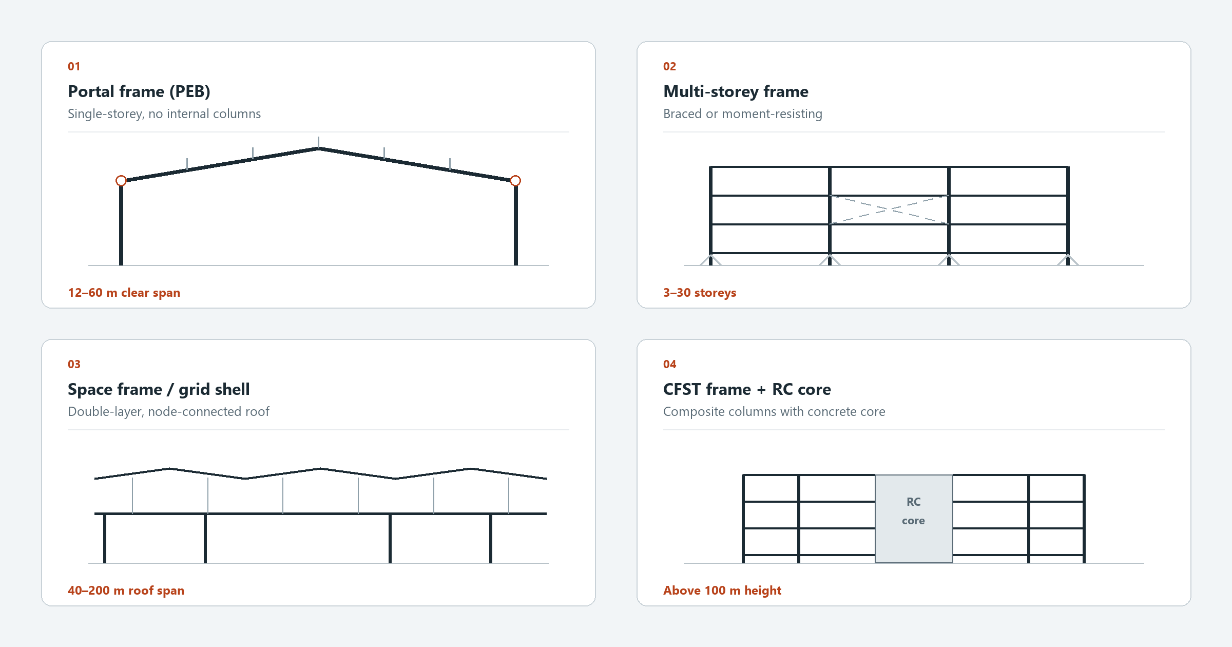
Design basis: AISC 360 or Eurocode 3
The project jurisdiction decides which family applies. So does the client specification and the EPC house standard. Loads follow ASCE 7-22 in US practice. EN 1991 governs in Europe and most of the Middle East, Africa and Central Asia. Seismic design follows AISC 341 or EN 1998-1. Execution class follows EN 1090-2. EXC2 covers most buildings, while EXC3 applies to bridges, high-seismicity frames and heavily cycled structures.
Mixing code families inside one package causes rework. A connection detailed to EN 1993-1-8 will not match a bolt schedule written to the RCSC Specification. The mismatch surfaces only at connection approval, which is late. We therefore lock one primary code family per package. We also record every deviation in the design basis document.
Detailing, BIM and the anchor bolt plan
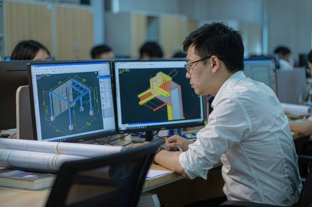
Therefore, detailing is a second design pass, not a drafting task. Its purpose is to make the frame fabricable, shippable, erectable and economical at the same time. Model coordination follows ISO 19650 information-management principles. We work the model to LOD 400, so bolts, stiffeners and weld access holes appear as real geometry rather than symbols.
Three checks at this stage prevent most site delays. First, clash resolution with civil, mechanical, electrical and fire-protection services. Second, weld access and bolt wrench clearance, verified in 3D rather than assumed on a 2D detail. Third, an anchor bolt setting plan issued before the foundation pour, with template frames and a stated positional tolerance of ±3 mm.
2. Stage 2: Fabrication, Coating and Logistics
In short, fabrication converts design intent into tolerance-controlled hardware. Material traceability, hole accuracy and trial assembly decide whether the frame closes on site.
Certificate and grade checks
Steel arrives with EN 10204 3.1 mill certificates. We re-check grade, heat number and impact properties against the drawing register. Common grades are S275 and S355J2 to EN 10025-2 for European and export markets. ASTM A992 or A572 Grade 50 covers US practice. Submerged-arc welded heavy sections often use S355J2+N or A913 Grade 65. For weldability, we normally hold carbon equivalent at or below 0.45. We also specify Charpy impact tests at 27 J at −20 °C for J2 material.
Fabrication limits that matter on site
| Parameter | Limit | Reference |
|---|---|---|
| Member length (shop) | ±2 mm | EN 1090-2 Annex D. |
| Straightness of welded columns | L/750 | EN 1090-2 Annex D. |
| Hole position within a group | ±1 mm | Shop drawing and AISC 303 practice. |
| Displacement between hole groups | 3 mm maximum | AISC 303. |
| Base plate flatness | 1 mm per 300 mm | EN 1090-2. |
| Mill certificate | EN 10204 3.1 with full traceability | EN 10204. |
CNC drilling rather than punching keeps hole quality predictable above 6 mm plate. Oversize or slotted holes appear only where the designer intends them. This rule matters, because an oversized hole silently converts a bearing connection into a slip-critical problem.
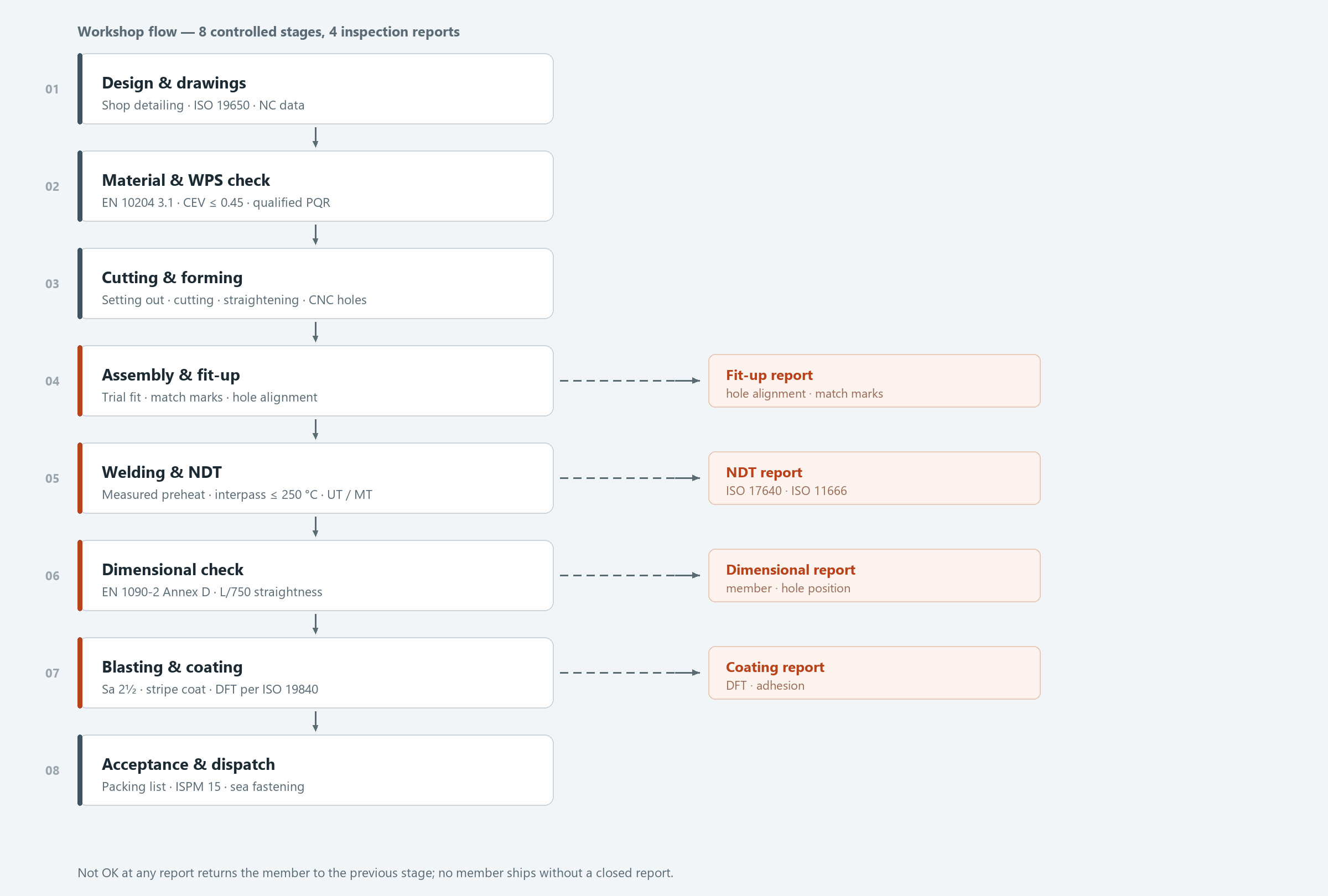
Trial assembly and transport engineering
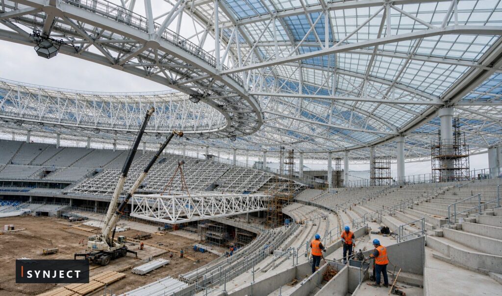
Complex nodes, skewed portals and stadium roof segments go through trial assembly in the shop. We pre-assemble bolted interfaces to confirm hole alignment, then mark match-numbers on every mating face. For example, we normally trial-fit a 60 m clear-span portal with tapered haunches in three sections. The knee joint is then proven before shipment.
Oversize members need a route survey before they need a crane. Where road transport is impossible, break-bulk design or water transport keeps the member within shippable limits. Packaging follows ISPM 15 for timber. Sea fastening follows the IMO CSS Code. Finally, each bundle carries a packing list keyed to the erection drawing, so the site team can stage steel by bay rather than by consignment.
3. Stage 3: Erection Sequencing by Structural Type
Erection is the point where steel structure construction becomes irreversible. In practice, sequence decisions taken here rarely reverse later. Sequence, temporary stability and survey frequency drive both safety and final geometry.
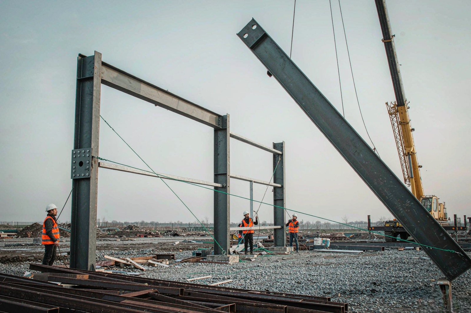
Single-storey portal frames
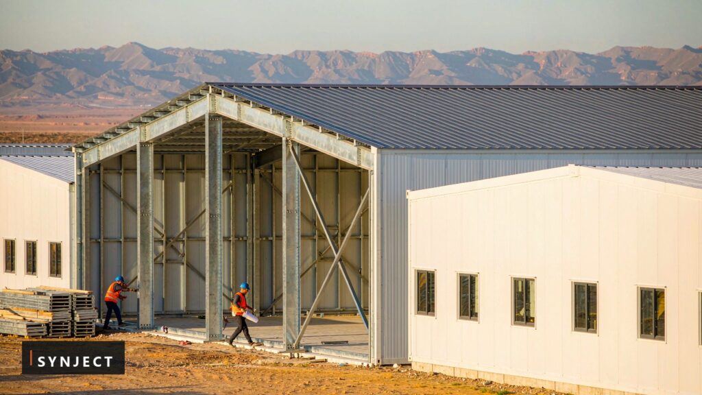
We erect the braced bay first, then complete bays in a controlled order. We plumb each frame and guy it temporarily before final bolt tightening. Purlins and fly braces follow immediately, because an unbraced portal is a mechanism rather than a structure. Moreover, we release temporary guys only after the permanent bracing set is complete and inspected.
Multi-storey frames
Multi-storey work usually leads the concrete core by three floors. As a result, the decking and concrete chase follow the steel. The survey team re-establishes column line after every third level. It uses an internal control method and transfers benchmarks through floor openings instead of relying on external sight lines. As a result, error does not accumulate with height.
Long-span roofs: integral lifting and cumulative sliding
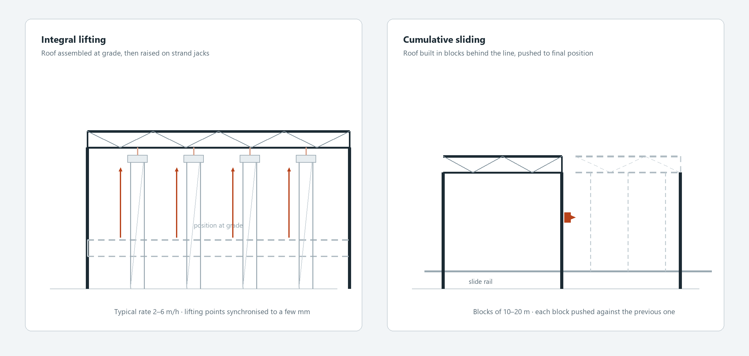
We assemble large roofs at grade and then move them. Working at height costs more and inspects worse. Two methods dominate.
- Integral lifting. Hydraulic strand jacks raise a completed roof from temporary support towers. Typical rate is 2–6 m per hour, with lifting points synchronised to a few millimetres. Engineers monitor load per jack and stop the lift if any point leaves the set envelope.
- Cumulative sliding. We assemble the roof in 10–20 m blocks behind the permanent line. Hydraulic jacks then push it forward on rails, block against block, until the full span closes.
Temporary towers, pre-camber and staged de-propping decide the final stress state. We usually set camber to the calculated dead-load deflection. We also simulate the release sequence before execution. Indeed, de-propping in the wrong order can double the moment in a girder designed for a single load path. We therefore release in stages: typically 25, 50, 75 and 100 percent of the support set. Deflection readings are taken at each stage.
Space frames
We assemble space frames outward from a fixed datum. Every node is set by three-dimensional coordinate rather than by tape. Bolted ball nodes and sleeve joints need a specified tightening torque, applied in the same rotational direction. That habit avoids imposing twist into the node.
4. Stage 4: Connection Integrity
Connections carry the frame, and they fail quietly. Accordingly, welding and high-strength bolting each need their own qualification trail.
Procedure, preheat and weld inspection
Every production weld runs on a qualified WPS backed by a procedure qualification record. Qualification follows ISO 15614-1 in European practice. AWS D1.1 Clause 4 governs in US practice. Welders hold ISO 9606-1 or AWS D1.1 Clause 6 certification for the position and process they use.
| Control | Typical specification |
|---|---|
| WPS and PQR | ISO 15614-1 or AWS D1.1 Clause 4. |
| Welder qualification | ISO 9606-1 or AWS D1.1 Clause 6. |
| Weld quality level | EN ISO 5817 level C at EXC2. Level B at EXC3. |
| Preheat, S355 at 20–40 mm | 80–150 °C, per EN 1090-2 Table 16 or AWS D1.1 Table 3.2. |
| Interpass temperature | Capped at 250 °C to protect toughness. |
| Heat input | 0.8–2.5 kJ/mm for FCAW and GMAW. Up to 4.0 kJ/mm for SAW. |
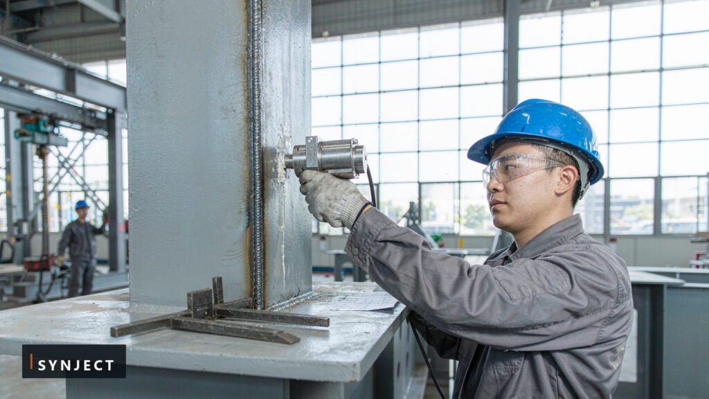
| Ultrasonic testing | ISO 17640, acceptance to ISO 11666. Scheduled at least 24 h after cooling. |
| NDT extent | About 5 percent at EXC2. 10 percent at EXC3. 100 percent on critical tension welds. |
Distortion control is a sequencing problem. We balance welding about the neutral axis, keep passes symmetric and avoid completing one side of a built-up member before the other. We measure preheat on the steel with a contact thermometer rather than infer it from ambient temperature. A cold plate pulls heat out of the arc faster than the procedure assumes.
High-strength bolting
Bolted connections fall into three families. Confusing them is a common and expensive error.
| Joint type | Method | Where it applies |
|---|---|---|
| Snug-tight bearing | Firm contact, no specified pretension | Secondary members, purlins, non-slip joints. |
| Pretensioned | Turn-of-nut, calibrated wrench, direct tension indicator or tension-control bolt | Moment connections and seismic framing. |
| Slip-critical | Pretensioned with faying surface slip factor of at least 0.50 | Oversize or slotted holes. Fatigue-sensitive joints. |
Bolt assemblies are ASTM F3125 Grade A325 or A490 in US practice. EN 14399-3 HR or EN 14399-4 HV system 10.9 covers European practice. Target preload is 0.70 of the bolt ultimate strength times the tensile stress area. We blast clean faying surfaces to Sa 2½ to ISO 8501-1 and leave them unpainted inside the joint. Paint destroys the friction coefficient.
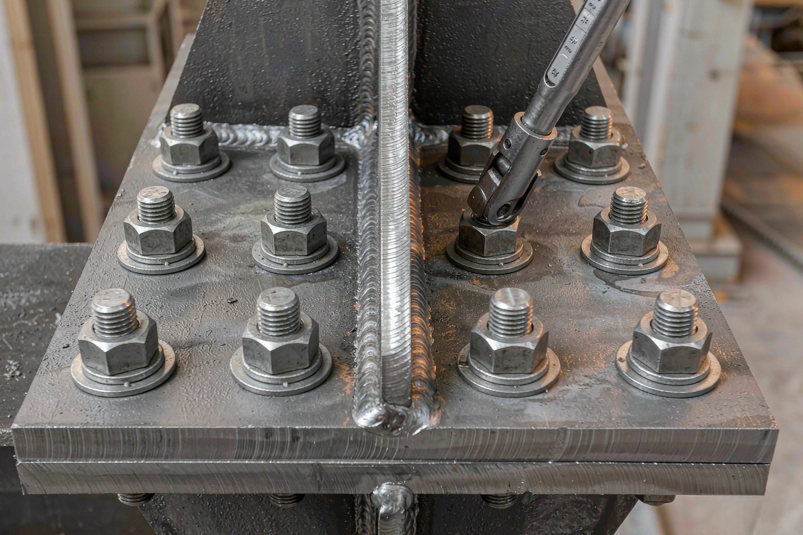
Tightening runs in two stages. A first pass brings the joint into contact. Final tightening then proceeds from the stiffest part of the connection outward. Moreover, high-strength bolts never serve as temporary erection bolts. Repeated use destroys the coating and the torque-tension relationship. We calibrate each wrench batch daily on a Skidmore-Wilhelm device and log the result against the bolt lot.
5. Stage 5: Decking, Corrosion Protection and Fire Protection
The structure does not finish with the last bolt. In practice, the envelope decides whether the frame survives its service life. Steel structure construction ends only when the envelope resists water, corrosion and fire as designed.
Metal decking and shear studs
Our crews set composite deck with correct end bearings and close the side laps before placing any concrete. We weld shear studs through the deck to EN ISO 14555 or AWS D1.1 Clause 9. The first studs of each shift are bent 30 degrees for a bend test. We also check deck loading during construction against the SDI or manufacturer span tables. A concrete buggy can overload an unpropped deck long before the slab reaches design strength.
Corrosion protection
Coating selection starts with the corrosivity category of the site, not with a standard thickness. ISO 12944-2 defines categories from C2 to C5, and ISO 12944-5 links each to a system.
| Category | Environment | Typical total dry film thickness |
|---|---|---|
| C3 | Urban and industrial, moderate SO₂ | 160–200 µm. |
| C4 | Coastal, industrial, high humidity | 240–280 µm. |
| C5 | Severe coastal, salt-laden or chemical | 320–400 µm. |
| Hot-dip galvanizing | External, maintenance-free exposure | 85 µm minimum average to EN ISO 1461 above 6 mm thickness. |
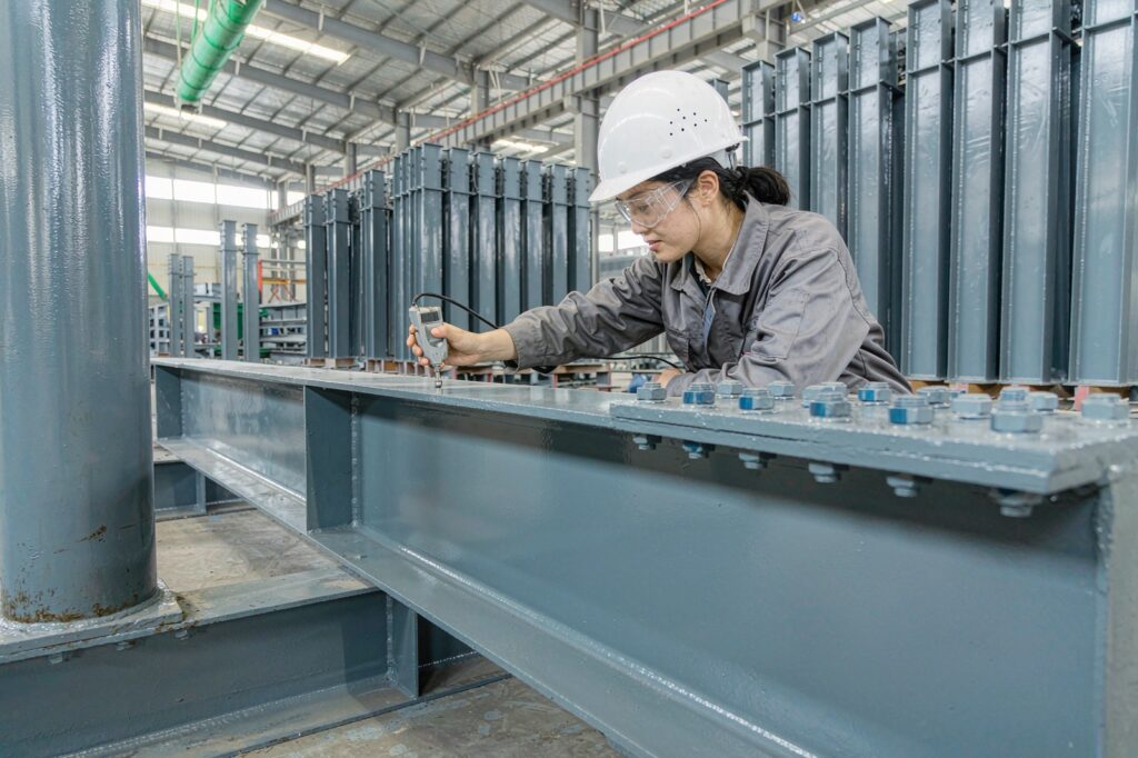
Surface preparation is Sa 2½ to ISO 8501-1 with a medium angular profile. Application stops when relative humidity exceeds 85 percent. It also stops when steel temperature sits within 3 °C of the dew point, since condensation under a fresh coat guarantees premature failure. The applicator stripe-coats welds, bolt heads and edges. We then measure dry film thickness to ISO 19840 using the 80 percent rule.
Fire protection
We specify intumescent coatings by fire resistance period and section factor. Each system is validated by furnace test to EN 13381-8. Boards and sprays follow EN 13381-4 or the national approval. A member rated R60 carries a much thinner film at a low section factor than at a high one. The applicator therefore works from a schedule keyed to each member size, not from an average thickness.